| Last Modified: 05-08-2025 | 6.11:8.1.0 | Doc ID: RM100000001EAAS |
| Model Year Start: 2019 | Model: RAV4 | Prod Date Range: [11/2018 - ] |
| Title: BRAKE CONTROL / DYNAMIC CONTROL SYSTEMS: ELECTRONICALLY CONTROLLED BRAKE SYSTEM (w/ Vacuum Brake Booster): C137BA2; Brake System Control Module "A" System Voltage System Voltage Low; 2019 - 2025 MY RAV4 RAV4 HV [11/2018 - ] | ||
|
DTC |
C137BA2 |
Brake System Control Module "A" System Voltage System Voltage Low |
DESCRIPTION
If a malfunction is detected in the power supply circuit, the skid control ECU (brake actuator assembly) stores this DTC and the fail-safe function prohibits ABS operation.
This DTC is stored when the +BS terminal voltage meets one of the DTC detection conditions due to a malfunction in the power supply or charging circuit such as the battery or alternator circuit, etc.
The DTC is cleared when the +BS terminal voltage returns to normal.
|
DTC No. |
Detection Item |
DTC Detection Condition |
Trouble Area |
|---|---|---|---|
|
C137BA2 |
Brake System Control Module "A" System Voltage System Voltage Low |
Any of the following is detected:
|
|
*: The skid control ECU (brake actuator assembly) monitors the resistance of the power source line at the +BS terminal. A malfunction is detected when an abnormality occurs in the +BS terminal wire harness or its connection and the skid control ECU (brake actuator assembly) determines that the wiring resistance at the +BS terminal exceeds the standard resistance.
DTC Detection Conditions: C137BA2
|
Vehicle Condition |
|||||||
|---|---|---|---|---|---|---|---|
|
Pattern 1 |
Pattern 2 |
Pattern 3 |
Pattern 4 |
Pattern 5 |
Pattern 6 |
||
|
Diagnosis Condition |
The vehicle speed is 6 km/h (4 mph) or more. |
○ |
○ |
- |
- |
- |
- |
|
The vehicle speed is 15 km/h (9 mph) or more and the +BS terminal voltage is 9.6 V or more. |
- |
- |
- |
○ |
- |
- |
|
|
The system has started. |
- |
- |
- |
- |
○ |
- |
|
|
Malfunction Status |
The +BS terminal voltage (soft low voltage) is less than 9.6 V. |
○ |
- |
- |
- |
- |
- |
|
The +BS terminal voltage (hard low voltage) is less than 6.9 V. |
- |
○ |
- |
- |
- |
- |
|
|
The +BS terminal voltage is less than 6.7 V and the skid control ECU (brake actuator assembly) judges that power supply voltage is abnormal. |
- |
- |
○ |
- |
- |
- |
|
|
The skid control ECU (brake actuator assembly) turns on more than one valve at the same time within a short period of time and the valve relay supply voltage drop exceeds the threshold.* |
- |
- |
- |
○ |
- |
- |
|
|
The +BS terminal voltage is less than 5 V. |
- |
- |
- |
- |
○ |
- |
|
|
The +BS terminal voltage is less than 2.6 V. |
- |
- |
- |
- |
- |
○ |
|
|
Detection Time |
1 second or more. |
1 second or more. |
0.06 seconds or more. |
- |
0.5 seconds or more. |
0.2 seconds or more. |
|
|
Number of Trips |
1 trip |
1 trip |
1 trip |
1 trip |
1 trip |
1 trip |
|
*: The skid control ECU (brake actuator assembly) monitors the resistance of the power source line at the +BS terminal. A malfunction is detected when an abnormality occurs in the +BS terminal wire harness or its connection and the skid control ECU (brake actuator assembly) determines that the wiring resistance at the +BS terminal exceeds the standard resistance.
HINT:
DTC will be output when conditions for either of the patterns in the table above are met.
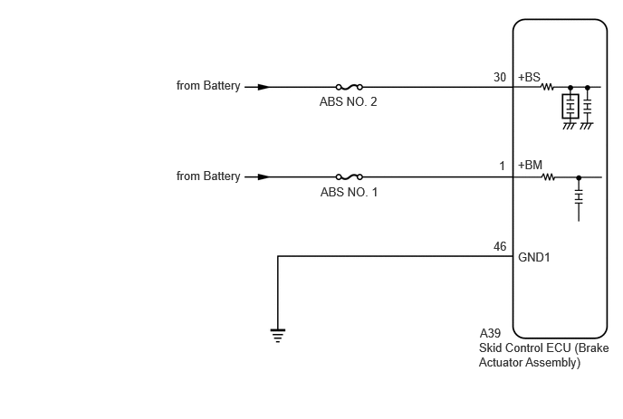
WIRING DIAGRAM
CAUTION / NOTICE / HINT
NOTICE:
- Inspect the fuses for circuits related to this system before performing the following procedure.
-
Before performing troubleshooting, make sure to confirm that the battery voltage is normal.
Click here
![2019 - 2025 MY RAV4 RAV4 HV [11/2018 - ]; INTRODUCTION: HOW TO TROUBLESHOOT ECU CONTROLLED SYSTEMS: HOW TO PROCEED WITH TROUBLESHOOTING](/t3Portal/stylegraphics/info.gif)
-
After replacing the skid control ECU (brake actuator assembly), perform acceleration sensor zero point calibration and store system information memorization.
Click here
PROCEDURE
|
1. |
CHECK FREEZE FRAME DATA (BS1 VOLTAGE VALUE AND MOTOR POWER SUPPLY VOLTAGE) |
(a) Select a DTC to display the Freeze Frame Data.
(b) Read the freeze frame data of DTC C137BA2.
Chassis > Brake/EPB
|
Tester Display |
Measurement Item |
Range |
Normal Condition |
Diagnostic Note |
|---|---|---|---|---|
|
BS1 Voltage Value |
+BS terminal voltage value (value detected by ECU) |
Min.: 0.0 V, Max.: 25.5 V |
Ignition switch ON: 11.0 to 14.0 V |
Changes in proportion to battery voltage HINT: This is the voltage detected at terminal +BS (which supplies power to each solenoid) of the skid control ECU (brake actuator assembly) |
|
Motor Power Supply Voltage |
+BM terminal voltage value (value detected by ECU) |
Min.: 0.0 V, Max.: 25.5 V |
Ignition switch ON: 11.0 to 14.0 V |
Changes in proportion to battery voltage HINT: This is the voltage detected at terminal +BM (which supplies power to the ABS motor) of the skid control ECU (brake actuator assembly) |
Chassis > Brake/EPB > DTC(C137BA2) > Freeze Frame Data
|
Tester Display |
|---|
|
BS1 Voltage Value |
|
Motor Power Supply Voltage |
|
Result |
Proceed to |
|---|---|
|
BS1 Voltage Value and Motor Power Supply Voltage are less than 9.6 V. |
A |
|
Only BS1 Voltage Value is less than 9.6 V. |
B |
|
Only Motor Power Supply Voltage is less than 9.6 V, or both BS1 Voltage Value and Motor Power Supply Voltage are 9.6 V or more. |
C |
| A |

|
CHECK OR REPLACE CHARGING SYSTEM COMPONENT OR BATTERY
|
| C |
|
REPLACE BRAKE ACTUATOR ASSEMBLY
|
|

|
2. |
READ VALUE USING GTS (BS1 VOLTAGE VALUE) |
(a) Start the engine.
(b) Follow the instructions on the screen to display the Data List, and perform the inspection.
Chassis > Brake/EPB > Data List
|
Tester Display |
Measurement Item |
Range |
Normal Condition |
Diagnostic Note |
|---|---|---|---|---|
|
BS1 Voltage Value |
+BS terminal voltage value (value detected by ECU) |
Min.: 0.0 V, Max.: 25.5 V |
Ignition switch ON: 11.0 to 14.0 V |
Changes in proportion to battery voltage HINT: This is the voltage detected at terminal +BS (which supplies power to each solenoid) of the skid control ECU (brake actuator assembly) |
Chassis > Brake/EPB > Data List
|
Tester Display |
|---|
|
BS1 Voltage Value |
|
Result |
Proceed to |
|---|---|
|
The value of BS1 Voltage Value is 9.6 V or more. |
A |
|
The value of BS1 Voltage Value is less than 9.6 V. |
B |
| A |
|
|
|
3. |
CHECK HARNESS AND CONNECTOR (+BS TERMINAL) |
|
(a) Make sure that there is no looseness at the locking part and the connecting part of the connector. OK: The connector is securely connected. |
|
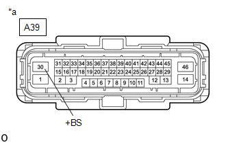
(b) Disconnect the A39 skid control ECU (brake actuator assembly) connector.
(c) Check both the connector case and the terminals for deformation and corrosion.
OK:
No deformation or corrosion.
(d) Measure the voltage according to the value(s) in the table below.
Standard Voltage:
|
Tester Connection |
Condition |
Specified Condition |
|---|---|---|
|
A39-30 (+BS) - Body ground |
Always |
9.6 V or higher |
| NG |
|
REPAIR OR REPLACE HARNESS OR CONNECTOR |
|
|
4. |
CHECK HARNESS AND CONNECTOR (GND1 TERMINAL) |
(a) Make sure that there is no looseness at the locking part and the connecting part of the connector.
OK:
The connector is securely connected.
(b) Disconnect the A39 skid control ECU (brake actuator assembly) connector.
(c) Check both the connector case and the terminals for deformation and corrosion.
OK:
No deformation or corrosion.
(d) Measure the resistance according to the value(s) in the table below.
Standard Resistance:
|
Tester Connection |
Condition |
Specified Condition |
|---|---|---|
|
A39-46 (GND1) - Body ground |
1 minute or more after disconnecting the cable from the negative (-) battery terminal |
Below 1 Ω |
| OK |
|
REPLACE BRAKE ACTUATOR ASSEMBLY
|
| NG |
|
REPAIR OR REPLACE HARNESS OR CONNECTOR |
|
|
|