| Last Modified: 11-18-2025 | 6.11:8.1.0 | Doc ID: RM100000001EKJ3 |
| Model Year Start: 2019 | Model: RAV4 HV | Prod Date Range: [11/2018 - 08/2020] |
| Title: HYBRID / BATTERY CONTROL: HYBRID CONTROL SYSTEM (for 2WD with NICKEL METAL HYDRIDE BATTERY): P0A1B94; Drive Motor "A" Control Module Unexpected Operation; 2019 - 2020 MY RAV4 HV [11/2018 - 08/2020] | ||
|
DTC |
P0A1B94 |
Drive Motor "A" Control Module Unexpected Operation |
DTC SUMMARY
MALFUNCTION DESCRIPTION
The hybrid vehicle control ECU assembly monitors the motor generator control ECU (MG ECU).
The cause of this malfunction may be the following:
Motor generator control ECU internal malfunction
- Motor generator control ECU (MG ECU) malfunction
DESCRIPTION
The hybrid vehicle control ECU assembly monitors the motor generator control ECU (MG ECU) and stores this DTC when it detects a malfunction.
|
DTC No. |
Detection Item |
DTC Detection Condition |
Trouble Area |
MIL |
Warning Indicate |
|---|---|---|---|---|---|
|
P0A1B94 |
Drive Motor "A" Control Module Unexpected Operation |
The motor generator control ECU (MG ECU) value received by the hybrid vehicle control ECU assembly exceeds the threshold for a certain period of time. (1 trip detection logic) |
|
Comes on |
Master Warning: Comes on |
CONFIRMATION DRIVING PATTERN
HINT:
After repair has been completed, clear the DTC and then check that the vehicle has returned to normal by performing the following All Readiness check procedure.
Click here
![2019 - 2020 MY RAV4 HV [11/2018 - 08/2020]; HYBRID / BATTERY CONTROL: HYBRID CONTROL SYSTEM (for 2WD with NICKEL METAL HYDRIDE BATTERY): UTILITY](/t3Portal/stylegraphics/info.gif)
- Connect the Techstream to the DLC3.
- Turn the power switch on (IG) and turn the Techstream on.
- Clear the DTCs (even if no DTCs are stored, perform the clear DTC procedure).
- Turn the power switch off and wait for 2 minutes or more.
- Turn the power switch on (IG) and turn the Techstream on.
-
With power switch on (IG) and wait for 2 minutes or more.
HINT:
If the vehicle has returned to normal, it can be driven after turning the power switch on (READY).
- Enter the following menus: Powertrain / Hybrid Control / Utility / All Readiness.
-
Check the DTC judgment result.
HINT:
- If the judgment result shows NORMAL, the system is normal.
- If the judgment result shows ABNORMAL, the system has a malfunction.
- If the judgment result shows INCOMPLETE, perform driving pattern again.
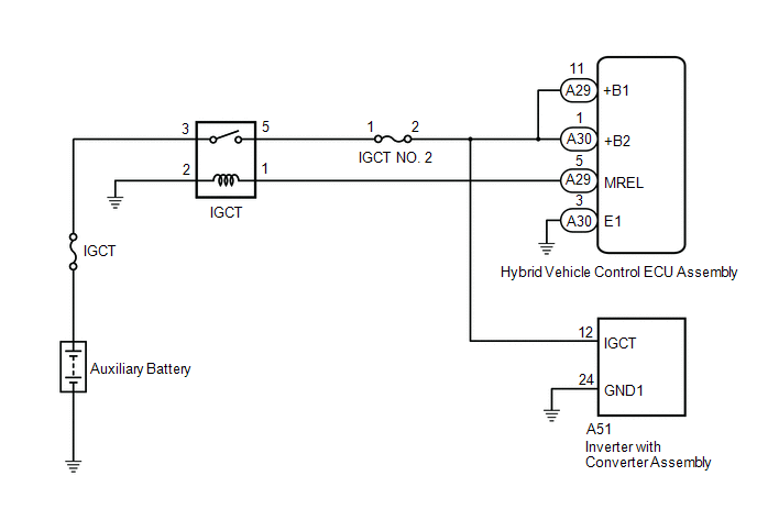
WIRING DIAGRAM
CAUTION / NOTICE / HINT
NOTICE:
After turning the power switch off, waiting time may be required before disconnecting the cable from the negative (-) auxiliary battery terminal. Therefore, make sure to read the disconnecting the cable from the negative (-) auxiliary battery terminal notices before proceeding with work.
Click here
PROCEDURE
PROCEDURE
|
1. |
CHECK AUXILIARY BATTERY TERMINAL (CONTACT PROBLEM) |
(a) Check the connection of the negative (-) and positive (+) auxiliary battery terminals.
OK:
The terminals are connected securely and there is no contact problem.
HINT:
If performing a simulation test, turn the power switch on (IG) and shake the wire harnesses vertically and horizontally before checking for DTCs.
| NG |

|
|

|
2. |
CHECK GROUND WIRE CONNECTION CONDITION |
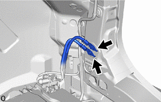
|
(a) Check the installation condition of the ground wires XA and XB. OK: The ground wires XA and XB are securely installed. HINT: If performing a simulation test, turn the power switch on (IG) and shake the wire harnesses vertically and horizontally before checking for DTCs. |
|
| NG |
|
|
|
3. |
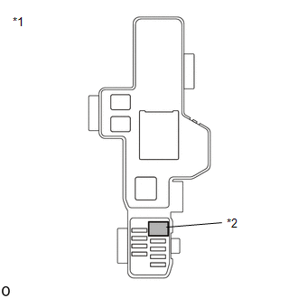
CHECK FUSE (IGCT) |
|
(a) Remove the IGCT fuse from the No. 3 relay block and junction block assembly. |
|
(b) Measure the resistance according to the value(s) in the table below.
Standard Resistance:
|
Tester Connection |
Condition |
Specified Condition |
|---|---|---|
|
IGCT fuse |
Always |
Below 1 Ω |
(c) Reinstall the IGCT fuse.
| NG |
|
|
|
4. |
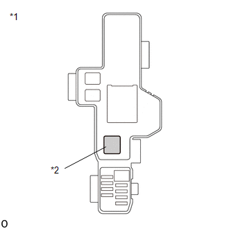
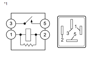
CHECK RELAY (IGCT) |
(a) Check the IGCT relay for improper installation.
OK:
The relay is installed securely.
HINT:
If performing a simulation test, turn the power switch on (IG) and gently vibrate the IGCT relay with a finger before checking for DTCs.
|
(b) Remove the IGCT relay from the No. 3 relay block and junction block assembly. |
|
|
(c) Measure the resistance according to the value(s) in the table below. Standard Resistance:
|
|
(d) Install the IGCT relay.
| NG |
|
|
|
5. |
CHECK DTC OUTPUT (HYBRID CONTROL) |
(a) Connect the Techstream to the DLC3.
(b) Turn the power switch on (IG).
(c) Enter the following menus: Powertrain / Hybrid Control / Trouble Codes.
(d) Check for DTCs.
HINT:
Check the DTCs that were output when the vehicle was brought to the workshop.
Powertrain > Hybrid Control > Trouble Codes
|
Result |
Proceed to |
|---|---|
|
P0A1B94 only is output. |
A |
|
DTCs except P0A1B94 are output. |
B |
(e) Turn the power switch off.
| A |
|
| B |
|
GO TO DTC CHART (HYBRID CONTROL SYSTEM)
Click here
|
|
6. |
CONNECT SECURELY |
| NEXT |
|
|
7. |
CONNECT SECURELY |
| NEXT |
|
|
8. |
REPAIR OR REPLACE MALFUNCTIONING PARTS |
| NEXT |
|
|
9. |
REPAIR OR REPLACE MALFUNCTIONING PARTS |
|
|
10. |
CLEAR DTC |
Click here
|
|
11. |
SIMULATION TEST |
(a) Turn the power switch off and wait for 2 minutes or more.
(b) Turn the power switch on (IG) and wait for 2 minutes or more.
(c) Turn the power switch off.
|
|
12. |
CHECK DTC OUTPUT (HYBRID CONTROL) |
(a) Connect the Techstream to the DLC3.
(b) Turn the power switch on (IG).
(c) Enter the following menus: Powertrain / Hybrid Control / Trouble Codes.
(d) Check for DTCs.
Powertrain > Hybrid Control > Trouble Codes
|
Result |
Proceed to |
|---|---|
|
No DTCs are output. |
A |
|
P0A1B94 only is output. |
B |
|
DTCs except P0A1B94 are output. |
C |
(e) Turn the power switch off.
| A |
|
END |
| B |
|
| C |
|
GO TO DTC CHART (HYBRID CONTROL SYSTEM)
Click here
|
|
|
|