| Last Modified: 11-18-2025 | 6.11:8.1.0 | Doc ID: RM100000001EKME |
| Model Year Start: 2019 | Model: RAV4 HV | Prod Date Range: [11/2018 - 08/2020] |
| Title: HYBRID / BATTERY CONTROL: MOTOR GENERATOR CONTROL SYSTEM (for 2WD with NICKEL METAL HYDRIDE BATTERY): P0A1112,P0A1114; DC/DC Converter Enable Circuit Short to Battery; 2019 - 2020 MY RAV4 HV [11/2018 - 08/2020] | ||
|
DTC |
P0A1112 |
DC/DC Converter Enable Circuit Short to Battery |
|
DTC |
P0A1114 |
DC/DC Converter Enable Circuit Short to Ground or Open |
DESCRIPTION
Refer to the description for DTC P1CCC96.
Click here
![2019 - 2020 MY RAV4 HV [11/2018 - 08/2020]; HYBRID / BATTERY CONTROL: MOTOR GENERATOR CONTROL SYSTEM (for 2WD with NICKEL METAL HYDRIDE BATTERY): P1CCC96; DC/DC Converter Enable Component Internal Failure+](/t3Portal/stylegraphics/info.gif)
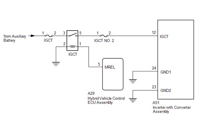
The motor generator control ECU sends a signal to the DC/DC converter to prohibit its control and receives signals indicating a normal or abnormal (below 11 V) condition of the 12 V charging system from the DC/DC converter via the NODD signal line.
If the vehicle is being driven with an inoperative DC/DC converter, the voltage of the auxiliary battery will drop, which will prevent the continued operation of the vehicle. Therefore, the motor generator control ECU monitors the operation of the DC/DC converter and alerts the driver if it detects a malfunction.
|
DTC No. |
Detection Item |
DTC Detection Condition |
Trouble Area |
MIL |
Warning Indicate |
|---|---|---|---|---|---|
|
P0A1112 |
DC/DC Converter Enable Circuit Short to Battery |
Short to +B detected in DC/DC converter NODD signal line (1 trip detection logic) |
|
Does not come on |
Master Warning: Comes on |
|
P0A1114 |
DC/DC Converter Enable Circuit Short to Ground or Open |
Open or short to ground detected in DC/DC converter NODD signal line (1 trip detection logic) |
|
Does not come on |
Master Warning: Comes on |
CONFIRMATION DRIVING PATTERN
HINT:
After repair has been completed, clear the DTC and then check that the vehicle has returned to normal by performing the following All Readiness check procedure.
Click here
- Connect the Techstream to the DLC3.
- Turn the power switch on (IG) and turn the Techstream on.
- Clear the DTCs (even if no DTCs are stored, perform the clear DTC procedure).
- Turn the power switch off and wait for 2 minutes or more.
- Turn the power switch on (IG) and turn the Techstream on.
- With power switch on (IG) and wait for 10 seconds or more.
- Enter the following menus: Powertrain / Motor Generator / Utility / All Readiness.
-
Check the DTC judgment result.
HINT:
- If the judgment result shows NORMAL, the system is normal.
- If the judgment result shows ABNORMAL, the system has a malfunction.
- If the judgment result shows INCOMPLETE, perform driving pattern again.
WIRING DIAGRAM
CAUTION / NOTICE / HINT
CAUTION:
-
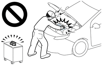
Before the following operations are conducted, take precautions to prevent electric shock by turning the power switch off, wearing insulated gloves, and removing the service plug grip from HV battery.
- Inspecting the high-voltage system
- Disconnecting the low voltage connector of the inverter with converter assembly
- Disconnecting the low voltage connector of the HV battery
-
To prevent electric shock, make sure to remove the service plug grip to cut off the high voltage circuit before servicing the vehicle.
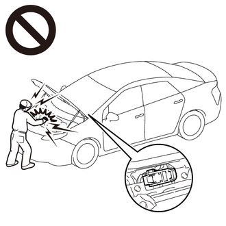
-
After removing the service plug grip from the HV battery, put it in your pocket to prevent other technicians from accidentally reconnecting it while you are working on the high-voltage system.
-
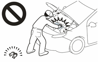
After removing the service plug grip, wait for at least 10 minutes before touching any of the high-voltage connectors or terminals. After waiting for 10 minutes, check the voltage at the terminals in the inspection point in the inverter with converter assembly. The voltage should be 0 V before beginning work.
Click here
HINT:
Waiting for at least 10 minutes is required to discharge the high-voltage capacitor inside the inverter with converter assembly.
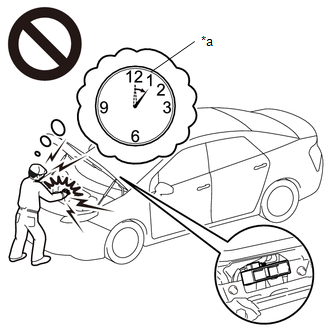
*a
Without waiting for 10 minutes
NOTICE:
After turning the power switch off, waiting time may be required before disconnecting the cable from the negative (-) auxiliary battery terminal. Therefore, make sure to read the disconnecting the cable from the negative (-) auxiliary battery terminal notices before proceeding with work.
Click here
HINT:
If the NODD signal line is open, DC/DC converter control will be prohibited and the auxiliary battery voltage will be approximately 12 V or less.
PROCEDURE
PROCEDURE
|
1. |
CHECK CONNECTOR CONNECTION CONDITION (INVERTER WITH CONVERTER ASSEMBLY CONNECTOR) |
Click here
|
Result |
Proceed to |
|---|---|
|
OK |
A |
|
NG (The connector is not connected securely.) |
B |
|
NG (The terminals are not making secure contact or are deformed, or water or foreign matter exists in the connector.) |
C |
| B |

|
CONNECT SECURELY |
| C |
|
REPAIR OR REPLACE HARNESS OR CONNECTOR |
|

|
2. |
CHECK HARNESS AND CONNECTOR (INVERTER WITH CONVERTER ASSEMBLY - IGCT RELAY) |
CAUTION:
Be sure to wear insulated gloves.
(a) Check that the service plug grip is not installed.
NOTICE:
After removing the service plug grip, do not turn the power switch on (READY), unless instructed by the repair manual because this may cause a malfunction.
(b) Disconnect the A51 inverter with converter assembly connector.
(c) Remove the IGCT relay from the No. 3 relay block and junction block assembly.
(d) Measure the resistance according to the value(s) in the table below.
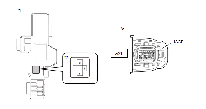
|
*1 |
No. 3 Relay Block and Junction Block Assembly |
*2 |
IGCT Relay |
|
*a |
Front view of wire harness connector (to Inverter with Converter Assembly) |
- |
- |
Standard Resistance:
|
Tester Connection |
Condition |
Specified Condition |
|---|---|---|
|
A51-12 (IGCT) - 5 (IGCT relay) |
Power switch off |
Below 1 Ω |
(e) Install the IGCT relay.
(f) Reconnect the A51 inverter with converter assembly connector.
| OK |
|
| NG |
|
REPAIR OR REPLACE HARNESS OR CONNECTOR |
|
|
|