- Inverter internal circuit malfunction
- Malfunction in ECU that controls the inverter
- Malfunction in the sensors for inverter control (current sensor, voltage sensors (VH, VL), etc.)
| Last Modified: 01-30-2024 | 6.11:8.1.0 | Doc ID: RM100000001EKNU |
| Model Year Start: 2019 | Model: RAV4 HV | Prod Date Range: [11/2018 - 08/2020] |
| Title: HYBRID / BATTERY CONTROL: MOTOR GENERATOR CONTROL SYSTEM (for 2WD with NICKEL METAL HYDRIDE BATTERY): P0E512A; DC/DC Converter Current Sensor Signal Stuck In Range; 2019 - 2020 MY RAV4 HV [11/2018 - 08/2020] | ||
|
DTC |
P0E512A |
DC/DC Converter Current Sensor Signal Stuck In Range |
DTC SUMMARY
MALFUNCTION DESCRIPTION
This DTC is stored if the value of the reactor current sensor does not change. The cause of this malfunction may be one of the following:
|
Area |
Main Malfunction Description |
|---|---|
|
Inverter |
|
|
HV battery high-voltage line circuit |
Open in an HV floor under wire |
DESCRIPTION
For a description of the boost converter.
Click here
![2019 - 2020 MY RAV4 HV [11/2018 - 08/2020]; HYBRID / BATTERY CONTROL: MOTOR GENERATOR CONTROL SYSTEM (for 2WD with NICKEL METAL HYDRIDE BATTERY): P0CA300; DC/DC Converter Step Up Voltage Performance+](/t3Portal/stylegraphics/info.gif)
|
DTC No. |
Detection Item |
DTC Detection Condition |
Trouble Area |
MIL |
Warning Indicate |
|---|---|---|---|---|---|
|
P0E512A |
DC/DC Converter Current Sensor Signal Stuck In Range |
The value of the reactor current sensor does not change. (1 trip detection logic) |
|
Comes on |
Master Warning: Comes on |
CONFIRMATION DRIVING PATTERN
HINT:
After repair has been completed, clear the DTC and then check that the vehicle has returned to normal by performing the following All Readiness check procedure.
Click here
- Connect the Techstream to the DLC3.
- Turn the power switch on (IG) and turn the Techstream on.
- Clear the DTCs (even if no DTCs are stored, perform the clear DTC procedure).
- Turn the power switch off and wait for 2 minutes or more.
- Apply the parking brake and secure the wheels using chocks.
- Turn the power switch on (IG) and turn the Techstream on.
- With power switch on (IG) and wait for 5 seconds or more.
- Turn the power switch on (READY).
- Move the shift lever to D.
-
Depress the brake pedal firmly with your left foot and fully depress the accelerator pedal for 5 seconds, and then release it.
NOTICE:
Make sure to fully apply the parking brake and firmly depress the brake pedal to prevent the vehicle from moving.
HINT:
If the engine starts before depressing the accelerator pedal, shift lever in P, wait until the engine stops, and then move the shift lever to D and repeat this step.
- Enter the following menus: Powertrain / Motor Generator / Utility / All Readiness.
-
Check the DTC judgment result.
HINT:
- If the judgment result shows NORMAL, the system is normal.
- If the judgment result shows ABNORMAL, the system has a malfunction.
- If the judgment result shows INCOMPLETE, perform driving pattern again.
WIRING DIAGRAM
Refer to the wiring diagram for the Inverter Low-voltage Circuit.
Click here
Refer to the wiring diagram for the HV Battery High-voltage Line Circuit.
Click here
CAUTION / NOTICE / HINT
CAUTION:
-
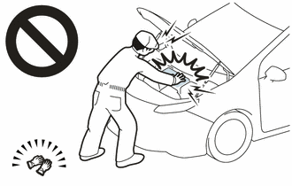
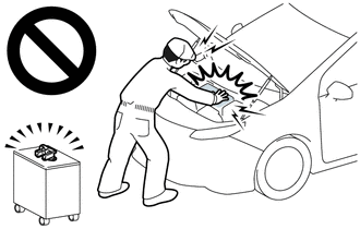
Before the following operations are conducted, take precautions to prevent electric shock by turning the power switch off, wearing insulated gloves, and removing the service plug grip from HV battery.
- Inspecting the high-voltage system
- Disconnecting the low voltage connector of the inverter with converter assembly
- Disconnecting the low voltage connector of the HV battery
-
To prevent electric shock, make sure to remove the service plug grip to cut off the high voltage circuit before servicing the vehicle.
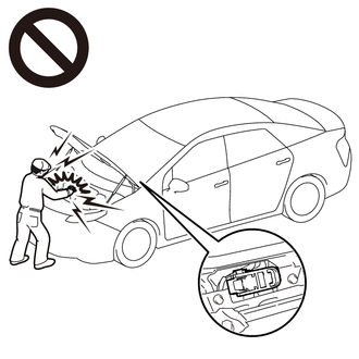
-
After removing the service plug grip from the HV battery, put it in your pocket to prevent other technicians from accidentally reconnecting it while you are working on the high-voltage system.
-
After removing the service plug grip, wait for at least 10 minutes before touching any of the high-voltage connectors or terminals. After waiting for 10 minutes, check the voltage at the terminals in the inspection point in the inverter with converter assembly. The voltage should be 0 V before beginning work.
Click here
HINT:
Waiting for at least 10 minutes is required to discharge the high-voltage capacitor inside the inverter with converter assembly.
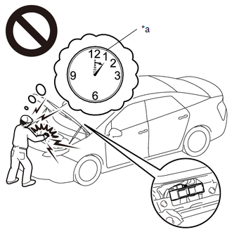
*a
Without waiting for 10 minutes
NOTICE:
After turning the power switch off, waiting time may be required before disconnecting the cable from the negative (-) auxiliary battery terminal. Therefore, make sure to read the disconnecting the cable from the negative (-) auxiliary battery terminal notices before proceeding with work.
Click here
PROCEDURE
|
1. |
CHECK DTC OUTPUT |
(a) Connect the Techstream to the DLC3.
(b) Turn the power switch on (IG).
(c) Enter the following menus: Powertrain / Hybrid Control and Motor Generator / Trouble Codes.
(d) Check for DTCs.
Powertrain > Hybrid Control > Trouble Codes
Powertrain > Motor Generator > Trouble Codes
|
Result |
Proceed to |
|---|---|
|
P0E512A only is output, or DTCs except the ones in the table below are also output. |
A |
|
DTCs of hybrid control system in the tables below are output. |
B |
|
DTCs of motor generator control system in the tables below are output. |
C |
Table 1
|
Malfunction Content |
System |
Relevant DTC |
|
|---|---|---|---|
|
Insulation Malfunction |
Hybrid control system |
P1C7C49 |
Hybrid/EV Battery Voltage System Isolation (A/C Area) Internal Electronic Failure |
|
P1C7D49 |
Hybrid/EV Battery Voltage System Isolation (Hybrid/EV Battery Area) Internal Electronic Failure |
||
|
P1C7E49 |
Hybrid/EV Battery Voltage System Isolation (Transaxle Area) Internal Electronic Failure |
||
|
P1C7F49 |
Hybrid/EV Battery Voltage System Isolation (Direct Current Area) Internal Electronic Failure |
||
|
System Main Relay or High Voltage Circuit Malfunction |
Hybrid control system |
P0AD911 |
Hybrid/EV Battery Positive Contactor Circuit Short to Ground |
|
P0AD915 |
Hybrid/EV Battery Positive Contactor Circuit Short to Auxiliary Battery or Open |
||
|
P0ADD11 |
Hybrid/EV Battery Negative Contactor Circuit Short to Ground |
||
|
P0ADD15 |
Hybrid/EV Battery Negative Contactor Circuit Short to Auxiliary Battery or Open |
||
|
P1C8449 |
High Voltage Power Resource Circuit Short during Ready ON |
||
|
HV Battery Malfunction |
Hybrid control system |
P0AFC16 |
Hybrid/EV Battery Sensor Module Circuit Voltage Below Threshold |
|
P0AFC96 |
Hybrid/EV Battery Sensor Module Component Internal Failure |
||
|
P1AC000 |
Hybrid/EV Battery Cell Low Voltage |
||
|
P1AD01B |
Hybrid/EV Battery Block Circuit Resistance Above Threshold |
||
|
P1CBE1E |
Hybrid/EV Battery Block 1 Voltage Difference Out of Range |
||
|
P1CBF1E |
Hybrid/EV Battery Block 2 Voltage Difference Out of Range |
||
|
P1CC01E |
Hybrid/EV Battery Block 3 Voltage Difference Out of Range |
||
|
P1CC11E |
Hybrid/EV Battery Block 4 Voltage Difference Out of Range |
||
|
P1CC21E |
Hybrid/EV Battery Block 5 Voltage Difference Out of Range |
||
|
P1CC31E |
Hybrid/EV Battery Block 6 Voltage Difference Out of Range |
||
|
P1CC41E |
Hybrid/EV Battery Block 7 Voltage Difference Out of Range |
||
|
P1CC51E |
Hybrid/EV Battery Block 8 Voltage Difference Out of Range |
||
|
P1CC61E |
Hybrid/EV Battery Block 9 Voltage Difference Out of Range |
||
|
P1CC71E |
Hybrid/EV Battery Block 10 Voltage Difference Out of Range |
||
|
P1CFD1E |
Hybrid/EV Battery Block 11 Voltage Difference Out of Range |
||
|
P301100 |
Hybrid/EV Battery Block 1 Circuit Resistance Out of Range (Extreme) |
||
|
P301200 |
Hybrid/EV Battery Block 2 Circuit Resistance Out of Range (Extreme) |
||
|
P301300 |
Hybrid/EV Battery Block 3 Circuit Resistance Out of Range (Extreme) |
||
|
P301400 |
Hybrid/EV Battery Block 4 Circuit Resistance Out of Range (Extreme) |
||
|
P301500 |
Hybrid/EV Battery Block 5 Circuit Resistance Out of Range (Extreme) |
||
|
P301600 |
Hybrid/EV Battery Block 6 Circuit Resistance Out of Range (Extreme) |
||
|
P301700 |
Hybrid/EV Battery Block 7 Circuit Resistance Out of Range (Extreme) |
||
|
P301800 |
Hybrid/EV Battery Block 8 Circuit Resistance Out of Range (Extreme) |
||
|
P301900 |
Hybrid/EV Battery Block 9 Circuit Resistance Out of Range (Extreme) |
||
|
P302000 |
Hybrid/EV Battery Block 10 Circuit Resistance Out of Range (Extreme) |
||
|
P302100 |
Hybrid/EV Battery Block 11 Circuit Resistance Out of Range (Extreme) |
||
|
U029A87 |
Lost Communication with Hybrid/EV Battery Sensor Module Missing Message |
||
Table 2
|
Malfunction Content |
System |
Relevant DTC |
|
|---|---|---|---|
|
Microcomputer malfunction |
Motor generator control system |
P0A1A47 |
Generator Control Module Watchdog / Safety MC Failure |
|
P0A1A49 |
Generator Control Module Internal Electronic Failure |
||
|
P0A1B1F |
Generator Control Module Circuit Intermittent |
||
|
P1C2A1C |
Generator A/D Converter Circuit Circuit Voltage Out of Range |
||
|
P1C2A49 |
Generator A/D Converter Circuit Internal Electronic Failure |
||
|
P1C2B1C |
Drive Motor "A" Control Module A/D Converter Circuit Voltage Out of Range |
||
|
P1C2B49 |
Drive Motor "A" Control Module A/D Converter Circuit Internal Electronic Failure |
||
|
P313383 |
Communication Error from Generator to Drive Motor "A" Value of Signal Protection Calculation Incorrect |
||
|
P313386 |
Communication Error from Generator to Drive Motor "A" Signal Invalid |
||
|
P313387 |
Communication Error from Generator to Drive Motor "A" Missing Message |
||
|
P313483 |
Communication Error from Drive Motor "A" to Generator Value of Signal Protection Calculation Incorrect |
||
|
P313486 |
Communication Error from Drive Motor "A" to Generator Signal Invalid |
||
|
P313487 |
Communication Error from Drive Motor "A" to Generator Missing Message |
||
|
Hybrid control system |
P0A1B49 |
Drive Motor "A" Control Module Internal Electronic Failure |
|
|
Power source circuit malfunction |
Motor generator control system |
P06B01C |
Generator Control Module Position Sensor REF Power Source Circuit Voltage Out of Range |
|
P06D61C |
Generator Control Module Offset Power Circuit Voltage Out of Range |
||
|
Communication malfunction |
Motor generator control system |
P312487 |
Lost Communication between Drive Motor "A" and HV ECU Missing Message |
|
Hybrid control system |
P312387 |
Lost Communication with Drive Motor Control Module "A" from Hybrid/EV Control Module Missing Message |
|
|
Sensor and actuator circuit malfunction |
Motor generator control system |
P0A3F16 |
Drive Motor "A" Position Sensor Circuit Voltage Below Threshold |
|
P0A3F21 |
Drive Motor "A" Position Sensor Signal Amplitude < Minimum |
||
|
P0A3F22 |
Drive Motor "A" Position Sensor Signal Amplitude > Maximum |
||
|
P0A4B16 |
Generator Position Sensor Circuit Voltage Below Threshold |
||
|
P0A4B21 |
Generator Position Sensor Signal Amplitude < Minimum |
||
|
P0A4B22 |
Generator Position Sensor Signal Amplitude > Maximum |
||
|
P0A6012 |
Drive Motor "A" Phase V Current (High Resolution) Circuit Short to Battery |
||
|
P0A6014 |
Drive Motor "A" Phase V Current (High Resolution) Circuit Short to Ground or Open |
||
|
P0A601C |
Drive Motor "A" Phase V Current (High Resolution) Circuit Voltage Out of Range |
||
|
P0A6312 |
Drive Motor "A" Phase W Current (High Resolution) Circuit Short to Battery |
||
|
P0A6314 |
Drive Motor "A" Phase W Current (High Resolution) Circuit Short to Ground or Open |
||
|
P0A631C |
Drive Motor "A" Phase W Current (High Resolution) Circuit Voltage Out of Range |
||
|
P0BE512 |
Drive Motor "A" Phase U Current Sensor Circuit Short to Battery |
||
|
P0BE514 |
Drive Motor "A" Phase U Current Sensor Circuit Short to Ground or Open |
||
|
P0BE528 |
Drive Motor "A" Phase U Current Sensor Signal Bias Level Out of Range / Zero Adjustment Failure |
||
|
P0BE912 |
Drive Motor "A" Phase V Current Sensor Circuit Short to Battery |
||
|
P0BE914 |
Drive Motor "A" Phase V Current Sensor Circuit Short to Ground or Open |
||
|
P0BE928 |
Drive Motor "A" Phase V Current Sensor Signal Bias Level Out of Range / Zero Adjustment Failure |
||
|
P0BED12 |
Drive Motor "A" Phase W Current Sensor Circuit Short to Battery |
||
|
P0BED14 |
Drive Motor "A" Phase W Current Sensor Circuit Short to Ground or Open |
||
|
P0BED28 |
Drive Motor "A" Phase W Current Sensor Signal Bias Level Out of Range / Zero Adjustment Failure |
||
|
P0BFD62 |
Drive Motor "A" Phase U-V-W Current Sensor Signal Compare Failure |
||
|
P0C5013 |
Drive Motor "A" Position Sensor Circuit "A" Circuit Open |
||
|
P0C5016 |
Drive Motor "A" Position Sensor Circuit "A" Circuit Voltage Below Threshold |
||
|
P0C5017 |
Drive Motor "A" Position Sensor Circuit "A" Circuit Voltage Above Threshold |
||
|
P0C5A13 |
Drive Motor "A" Position Sensor Circuit "B" Circuit Open |
||
|
P0C5A16 |
Drive Motor "A" Position Sensor Circuit "B" Circuit Voltage Below Threshold |
||
|
P0C5A17 |
Drive Motor "A" Position Sensor Circuit "B" Circuit Voltage Above Threshold |
||
|
P0C6413 |
Generator Position Sensor Circuit "A" Circuit Open |
||
|
P0C6416 |
Generator Position Sensor Circuit "A" Circuit Voltage Below Threshold |
||
|
P0C6417 |
Generator Position Sensor Circuit "A" Circuit Voltage Above Threshold |
||
|
P0C6913 |
Generator Position Sensor Circuit "B" Circuit Open |
||
|
P0C6916 |
Generator Position Sensor Circuit "B" Circuit Voltage Below Threshold |
||
|
P0C6917 |
Generator Position Sensor Circuit "B" Circuit Voltage Above Threshold |
||
|
P0D2D16 |
Drive Motor "A" Inverter Voltage Sensor (VH) Circuit Voltage Below Threshold |
||
|
P0D2D17 |
Drive Motor "A" Inverter Voltage Sensor (VH) Circuit Voltage Above Threshold |
||
|
P0DFA62 |
Generator Phase U-V-W Current Sensor Signal Compare Failure |
||
|
P0E0012 |
Generator Phase U Current Sensor Circuit Short to Battery |
||
|
P0E0014 |
Generator Phase U Current Sensor Circuit Short to Ground or Open |
||
|
P0E0028 |
Generator Phase U Current Sensor Signal Bias Level Out of Range / Zero Adjustment Failure |
||
|
P0E0412 |
Generator Phase V Current Sensor Circuit Short to Battery |
||
|
P0E0414 |
Generator Phase V Current Sensor Circuit Short to Ground or Open |
||
|
P0E0428 |
Generator Phase V Current Sensor Signal Bias Level Out of Range / Zero Adjustment Failure |
||
|
P0E0812 |
Generator Phase W Current Sensor Circuit Short to Battery |
||
|
P0E0814 |
Generator Phase W Current Sensor Circuit Short to Ground or Open |
||
|
P0E0828 |
Generator Phase W Current Sensor Signal Bias Level Out of Range / Zero Adjustment Failure |
||
|
P0E3116 |
DC/DC Converter Voltage Sensor "A" (VL) Circuit Voltage Below Threshold |
||
|
P0E3117 |
DC/DC Converter Voltage Sensor "A" (VL) Circuit Voltage Above Threshold |
||
|
P0E5111 |
DC/DC Converter Current Sensor Circuit Short to Ground |
||
|
P0E5115 |
DC/DC Converter Current Sensor Circuit Short to Battery or Open |
||
|
P1CAC49 |
Generator Position Sensor Internal Electronic Failure |
||
|
P1CAD49 |
Drive Motor "A" Position Sensor Internal Electronic Failure |
||
|
P1CAF38 |
Generator Position Sensor REF Signal Cycle Malfunction Signal Frequency Incorrect |
||
|
P1CB038 |
Drive Motor "A" Position Sensor REF Signal Frequency Incorrect |
||
|
Hybrid control system |
P0C7600 |
Hybrid/EV Battery System Discharge Time Too Long |
|
|
P0D2D1C |
Drive Motor "A" Inverter Voltage Sensor Voltage Out of Range |
||
|
P0E311C |
Boosting Converter Voltage Sensor "A" Voltage Out of Range |
||
|
System Malfunction |
Motor generator control system |
P0A9000 |
Drive Motor "A" Performance |
|
P0A9200 |
Hybrid Generator Performance |
||
|
P0BFF1D |
Drive Motor "A" Circuit Current Out of Range |
||
|
P0C1900 |
Drive Motor "A" Execution Torque Performance |
||
|
P0CA300 |
DC/DC Converter Step Up Voltage Performance |
||
|
P0E7100 |
Generator Execution Torque Performance |
||
|
P1CA51D |
Hybrid Generator Circuit Current Out of Range |
||
|
Hybrid control system |
P0AA649 |
Hybrid/EV Battery Voltage System Isolation Internal Electronic Failure |
|
HINT:
-
P0E512A may be output as a result of the malfunction indicated by the DTCs above.
- The chart above is listed in inspection order of priority.
- Check DTCs that are output at the same time by following the listed order. (The main cause of the malfunction can be determined without performing unnecessary inspections.)
(e) Turn the power switch off.
| B |

|
GO TO DTC CHART (HYBRID CONTROL SYSTEM)
|
| C |
|
|

|
2. |
CHECK CONNECTOR CONNECTION CONDITION (INVERTER WITH CONVERTER ASSEMBLY CONNECTOR) |
Click here
|
Result |
Proceed to |
|---|---|
|
OK |
A |
|
NG (The connector is not connected securely.) |
B |
|
NG (The terminals are not making secure contact or are deformed, or water or foreign matter exists in the connector.) |
C |
| B |
|
CONNECT SECURELY |
| C |
|
REPAIR OR REPLACE HARNESS OR CONNECTOR |
|
|
3. |
CHECK HV BATTERY HIGH-VOLTAGE LINE CIRCUIT |
Click here
|
|
4. |
CHECK INVERTER LOW-VOLTAGE CIRCUIT |
Click here
HINT:
If the "Inverter Low-voltage Circuit" inspection results are normal, perform the next step.
| NEXT |
|
REPLACE INVERTER WITH CONVERTER ASSEMBLY
|
|
|
|