| 
                           Last Modified: 05-08-2025 | 
                        6.11:8.1.0  | 
                        
                           Doc ID: RM100000001EPGF | 
                      
                     
                        | 
                           Model Year Start: 2019 | 
                        
                           Model: RAV4 | 
                        
                           Prod Date Range: [11/2018 -                    
                                       ] | 
                      
                     
                        | 
                           Title: LIGHTING (EXT): STOP LIGHT SWITCH: INSTALLATION; 2019 - 2025 MY RAV4 RAV4 HV [11/2018 -        ] | 
                      
                   
                  INSTALLATION
                   
                  PROCEDURE
                   
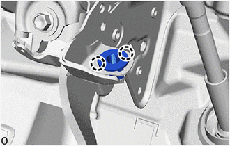
                  1. INSTALL STOP LIGHT SWITCH MOUNTING ADJUSTER 


                           | 
                               (a) Attach the claw to install a new stop light switch mounting adjuster. 
                            | 
                           
                              
                            | 


                  2. INSTALL STOP LIGHT SWITCH ASSEMBLY 


                           | 
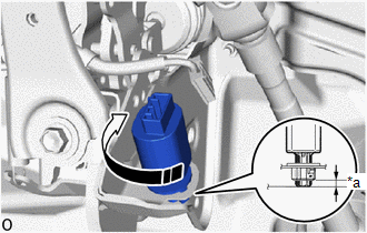
                               (a) Insert the stop light switch assembly to the stop light switch mounting adjuster until the switch body slightly touches the brake pedal. 
                              NOTICE: 
                              Do not depress the brake pedal. 
                            | 
                           
                              
                            | 


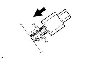
                  (b) Turn the stop light switch assembly clockwise by approximately one fourth of a rotation. 


                           | 
                               *a 
                            | 
                           
                               Protrusion Amount Measurement Area 
                            | 


                            | 
                           
                               Turn in this Direction 
                            | 


                  (c) Check the protrusion amount of the shaft. 
                  Standard:  
                  0.5 to 2.6 mm (0.0197 to 0.1024 in.) 


                           | 
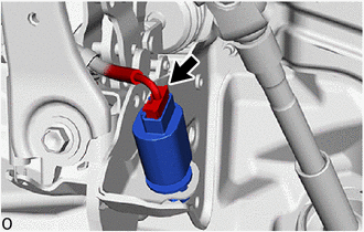
                               (d) Connect the connector. 
                            | 
                           
                              
                            | 


                  3. INSTALL NO. 1 INSTRUMENT PANEL UNDER COVER SUB-ASSEMBLY 
                  Click here


                |