| 
                           Last Modified: 05-08-2025 | 
                        6.11:8.1.0  | 
                        
                           Doc ID: RM100000001FH9X | 
                      
                     
                        | 
                           Model Year Start: 2019 | 
                        
                           Model: RAV4 HV | 
                        
                           Prod Date Range: [11/2018 - 02/2019] | 
                      
                     
                        | 
                           Title: HYBRID / BATTERY CONTROL: FRAME WIRE: INSTALLATION; 2019 MY RAV4 HV [11/2018 - 02/2019] | 
                      
                   
                  INSTALLATION
                   
                  PROCEDURE
                   
                  1. INSTALL HV FLOOR UNDER WIRE 
                  CAUTION: 
                  Be sure to wear insulated gloves. 


                           | 
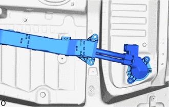
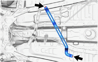
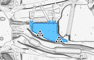
                               (a) Insert the HV floor under wire into the floor panel hole and engage the grommet. 
                            | 
                           
                              
                            | 


                           | 
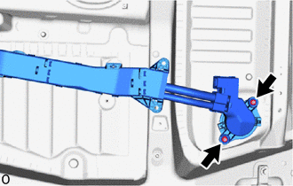
                               (b) Install the 2 nuts. 
                              Torque:  
                              8.0 N·m {82 kgf·cm, 71 in·lbf} 
                            | 
                           
                              
                            | 


                           | 
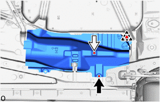
                               (c) Install a new 2 stud clamps. 
                            | 
                           
                              
                            | 


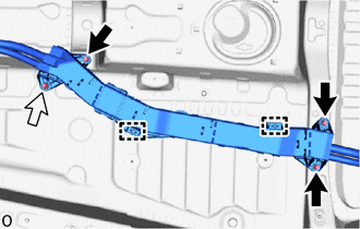
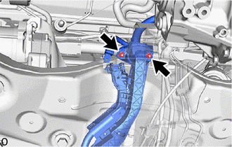
                  (d) Install the 3 bolts and nut. 
                  Torque:  
                  8.0 N·m {82 kgf·cm, 71 in·lbf} 


                           | 
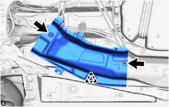
                               (e) Install a new 2 stud clamps. 
                            | 
                           
                              
                            | 


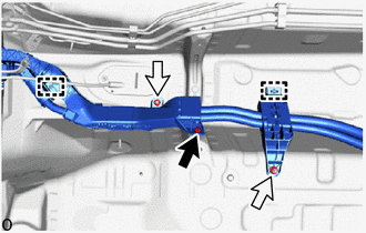
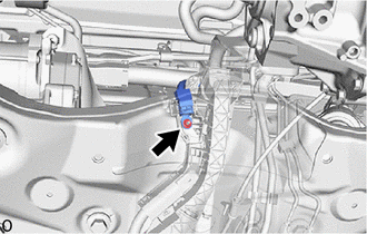
                  (f) Install the bolt and 2 nuts. 
                  Torque:  
                  8.0 N·m {82 kgf·cm, 71 in·lbf} 


                           | 
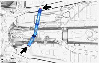
                               (g) Install the 2 nuts. 
                              Torque:  
                              8.0 N·m {82 kgf·cm, 71 in·lbf} 
                            | 
                           
                              
                            | 


                           | 
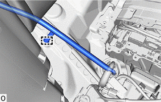
                               (h) Connect the engine room main wire to the vehicle body with the nut. 
                              Torque:  
                              8.0 N·m {82 kgf·cm, 71 in·lbf} 
                            | 
                           
                              
                            | 


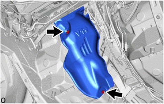
                  (i) Engage the guide and 2 claws to install the No. 1 terminal cap. 


                            | 
                           
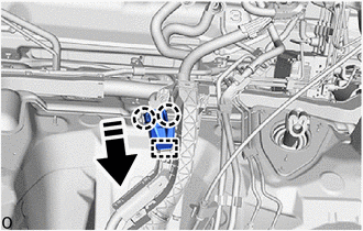
                               Install in this Direction 
                            | 


                  2. INSTALL FUEL TANK ASSEMBLY 
                  Click here


                  3. INSTALL EXHAUST MANIFOLD 
                  Click here


                  4. INSTALL FRONT EXHAUST PIPE ASSEMBLY 
                  Click here


                  5. CONNECT TRANSMISSION CONTROL CABLE ASSEMBLY 
                  (a) Connect the transmission control cable assembly to the vehicle body with the nut. 
                  Torque:  
                  6.0 N·m {61 kgf·cm, 53 in·lbf} 
                   
                  6. INSTALL ENGINE SERVICE COVER CUSHION 


                           | 
                               (a) Install the engine service cover cushion with the 2 nuts. 
                              Torque:  
                              4.9 N·m {50 kgf·cm, 43 in·lbf} 
                            | 
                           
                              
                            | 


                  7. INSTALL NO. 2 ENGINE SERVICE COVER CUSHION 


                           | 
                               (a) Install the No. 2 engine service cover cushion with the 2 nuts. 
                              Torque:  
                              4.9 N·m {50 kgf·cm, 43 in·lbf} 
                            | 
                           
                              
                            | 


                  8. INSTALL FRONT NO. 1 FLOOR HEAT INSULATOR 


                           | 
                               (a) Install the front No. 1 floor heat insulator with the 2 nuts. 
                              Torque:  
                              4.9 N·m {50 kgf·cm, 43 in·lbf} 
                            | 
                           
                              
                            | 


                  9. INSTALL FRONT LOWER NO. 1 FLOOR HEAT INSULATOR 


                           | 
                               (a) Install the front lower No. 1 floor heat insulator with the nut and bolt. 
                              Torque:  
                              4.9 N·m {50 kgf·cm, 43 in·lbf} 
                            | 
                           
                              
                            | 


                  (b) Install the clip. 
                   
                  10. INSTALL FRONT NO. 2 FLOOR HEAT INSULATOR 


                           | 
                               (a) Install the front No. 2 floor heat insulator with the 2 nuts. 
                              Torque:  
                              4.9 N·m {50 kgf·cm, 43 in·lbf} 
                            | 
                           
                              
                            | 


                  (b) Install the clip. 
                   
                  11. INSTALL FRONT CENTER FLOOR COVER 


                           | 
                               (a) Install the front center floor cover with the 2 clips. 
                            | 
                           
                              
                            | 


                  12. INSTALL FRONT FLOOR COVER RH 
                  Click here


                  13. INSTALL FRONT FLOOR COVER LH 
                  Click here


                  14. INSTALL ENGINE UNDER COVER HEAT INSULATOR 
                  Click here


                  15. INSTALL NO. 2 ENGINE UNDER COVER ASSEMBLY 
                  Click here


                  16. INSTALL NO. 1 ENGINE UNDER COVER 
                  Click here


                  17. INSTALL FRONT FENDER FRONT SPLASH SHIELD RH 
                  Click here


                  18. INSTALL FRONT FENDER FRONT SPLASH SHIELD LH 
                  Click here


                  19. INSTALL FRONT WHEELS 
                  Click here


                  20. CONNECT HV FLOOR UNDER WIRE 
                  CAUTION: 
                  Be sure to wear insulated gloves. 


                           | 
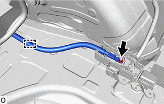
                               (b) Install the HV under floor wire with the nut. 
                              Torque:  
                              7.6 N·m {77 kgf·cm, 67 in·lbf} 
                            | 
                           
                              
                            | 


                  (c) Engage the clamp. 


                           | 
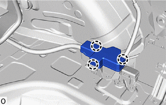
                               (d) Engage the 3 claws to install the No. 4 relay block cover. 
                            | 
                           
                              
                            | 


                  (e) Connect the shield ground to the HV battery. 
                  (f) Connect the 2 HV battery junction block assembly connectors. 
                  NOTICE: 
                  Make sure that the connectors are connected securely. 
                   
                  21. INSTALL NO. 1 HV BATTERY COVER PANEL RH 
                  Click here


                  22. INSTALL REAR SEAT CUSHION LEG SUB-ASSEMBLY 
                  Click here


                  23. INSTALL BATTERY SERVICE COVER BOARD 
                  Click here


                  24. INSTALL NO. 2 BATTERY SERVICE COVER BOARD 
                  Click here


                  25. INSTALL REAR DOOR SCUFF PLATE LH 
                  Click here


                  26. INSTALL NO. 3 BATTERY SERVICE COVER BOARD 
                  Click here


                  27. INSTALL REAR DOOR SCUFF PLATE RH 
                  HINT: 
                  Use the same procedure as for the LH side. 
                   
                  28. INSTALL REAR SEAT CUSHION LOCK HOOK 
                  Click here


                  29. INSTALL BENCH TYPE REAR SEAT CUSHION ASSEMBLY 
                  Click here


                  30. CONNECT HV FLOOR UNDER WIRE 
                  Click here


                  31. CONNECT ENGINE ROOM MAIN WIRE 
                  CAUTION: 
                  Be sure to wear insulated gloves. 
                  NOTICE: 
                  Do not allow any foreign matter or water to enter the inverter with converter assembly. 
                  (a) Connect the inverter with converter assembly connector and move the lock lever to lock them. 
                  
                     NOTICE: 
                     
                        - 
Do not touch the waterproof seal or terminals of the connectors.
 
                        - 
To prevent damage due to static electricity, do not touch the terminals of the disconnected connectors.
 
                        - 
Do not damage the terminals, connector housing or inverter with converter assembly when connecting the connectors.


                  32. INSTALL SERVICE PLUG GRIP 
                  Click here


                |