| 
                           Last Modified: 05-08-2025 | 
                        6.11:8.1.0  | 
                        
                           Doc ID: RM100000001FH9Z | 
                      
                     
                        | 
                           Model Year Start: 2019 | 
                        
                           Model: RAV4 HV | 
                        
                           Prod Date Range: [11/2018 - 02/2019] | 
                      
                     
                        | 
                           Title: HYBRID / BATTERY CONTROL: FRAME WIRE: REMOVAL; 2019 MY RAV4 HV [11/2018 - 02/2019] | 
                      
                   
                  REMOVAL
                   
                  CAUTION / NOTICE / HINT
                  The necessary procedures (adjustment, calibration, initialization, or registration) that must be performed after parts are removed and installed, or replaced during HV floor under wire removal/installation are shown below. 
                  Necessary Procedures After Parts Removed/Installed/Replaced


                           | 
                               Replaced Part or Performed Procedure 
                            | 
                           
                               Necessary Procedures 
                            | 
                           
                               Effect/Inoperative Function when Necessary Procedure not Performed 
                            | 
                           
                               Link 
                            | 


                           | 
                               Auxiliary battery terminal is disconnected/reconnected 
                            | 
                           
                               Perform steering sensor zero point calibration 
                            | 
                           
                               Lane control system 
                            | 


                            | 
                         
                        
                           | 
                               Pre-collision system 
                            | 
                         
                        
                           | 
                               Memorize steering angle neutral point 
                            | 
                           
                               Parking assist monitor system 
                            | 


                            | 
                         
                        
                           | 
                               Panoramic view monitor system 
                            | 


                            | 
                         
                        
                           | 
                               Reset back door close position 
                            | 
                           
                               Power back door system 
                            | 


                            | 
                         
                        
                           | 
                               Back door lock initialization 
                            | 
                           
                               Power door lock control system 
                            | 


                            | 


                                    - 
Replacement of air fuel ratio sensor
 
                                    - 
Gas leak from exhaust system is repaired


                            | 
                           
                               Inspection After Repair 
                            | 


                                    - 
Poor idle, etc.
 
                                    - 
Engine start function, etc.


                            | 


                            | 


                  NOTICE: 
                  After the power switch is turned off, the radio and display receiver assembly records various types of memory and settings. As a result, after turning the power switch off, be sure to wait for the time specified in the following table before disconnecting the cable from the negative (-) auxiliary battery terminal. 
                  Waiting Time before Disconnecting Cable from Negative (-) Auxiliary Battery Terminal


                           | 
                               System Name 
                            | 
                           
                               See Procedure 
                            | 


                           | 
                               Vehicle enrolled in Toyota Entune system or safety connect system 
                            | 
                           
                               6 minutes 
                            | 
                         
                        
                           | 
                               Vehicle not enrolled in Toyota Entune system and safety connect system 
                            | 
                           
                               1 minute 
                            | 


                  PROCEDURE
                   
                  1.   PRECAUTION 
                  NOTICE: 
                  After turning the power switch off, waiting time may be required before disconnecting the cable from the negative (-) auxiliary battery terminal. Therefore, make sure to read the disconnecting the cable from the negative (-) auxiliary battery terminal notices before proceeding with work. 
                   
                  2. REMOVE SERVICE PLUG GRIP 
                  Click here


                  3. DISCONNECT ENGINE ROOM MAIN WIRE 
                  CAUTION: 
                  Be sure to wear insulated gloves. 
                  NOTICE: 
                  Do not allow any foreign matter or water to enter the inverter with converter assembly. 


                           | 
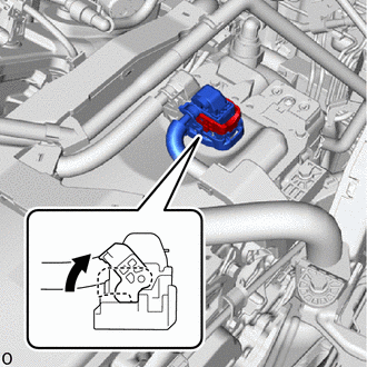
                               (a) Move the lock lever while pushing the lock on the connector, and disconnect the inverter with converter assembly connector. 
                              
                                 NOTICE: 
                                 
                                    - 
Do not damage the terminals, connector housing or inverter with converter assembly during disconnection.
 
                                    - 
Cover the hole where the cable was connected with tape (non-residue type) or equivalent to prevent entry of foreign matter.
 
                                    - 
Insulate the disconnected terminals with insulating tape.
 
                                    - 
Do not touch the waterproof seal or terminals of the connector.


                            | 
                           
                              
                            | 


                  4. REMOVE CONNECTOR COVER ASSEMBLY 
                  Click here


                  5. CHECK TERMINAL VOLTAGE 
                  Click here


                  6. TEMPORARILY INSTALL CONNECTOR COVER ASSEMBLY 
                  Click here


                  7. DISCONNECT HV FLOOR UNDER WIRE 
                  Click here


                  8. REMOVE BENCH TYPE REAR SEAT CUSHION ASSEMBLY 
                  Click here


                  9. REMOVE REAR SEAT CUSHION LOCK HOOK 
                  Click here


                  10. REMOVE REAR DOOR SCUFF PLATE LH 
                  Click here


                  11. REMOVE NO. 3 BATTERY SERVICE COVER BOARD 
                  Click here


                  12. REMOVE REAR DOOR SCUFF PLATE RH 
                  HINT: 
                  Use the same procedure as for the LH side. 
                   
                  13. REMOVE NO. 2 BATTERY SERVICE COVER BOARD 
                  Click here


                  14. REMOVE BATTERY SERVICE COVER BOARD 
                  Click here


                  15. REMOVE REAR SEAT CUSHION LEG SUB-ASSEMBLY 
                  Click here


                  16. REMOVE NO. 1 HV BATTERY COVER PANEL RH 
                  Click here


                  17. DISCONNECT HV FLOOR UNDER WIRE 
                  CAUTION: 
                  Be sure to wear insulated gloves. 


                           | 
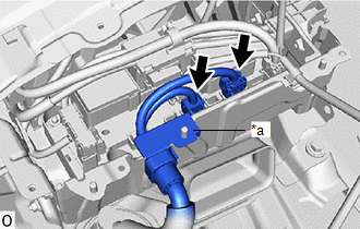
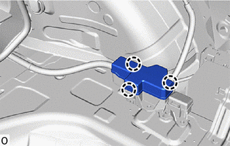
                               (a) Disconnect the 2 HV battery junction block assembly connectors. 
                              NOTICE: 
                              Insulate each disconnected high-voltage connector with insulating tape. Wrap the connector from the wire harness side to the end of the connector. 
                            | 
                           
                              
                            | 


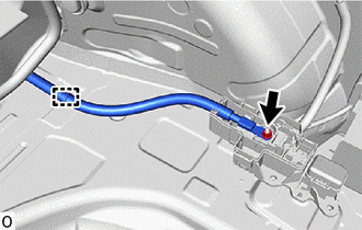
                  (b) Disconnect the shield ground from the HV battery. 


                           | 
                               (c) Disengage the 3 claws to remove the No. 4 relay block cover. 
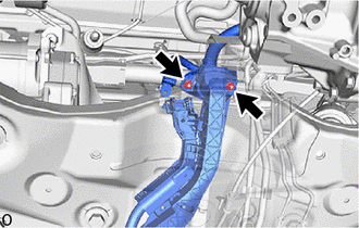
                            | 
                           
                              
                            | 


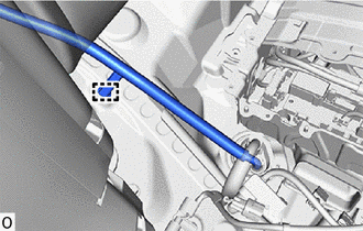
                  (e) Disengage the clamp. 


                           | 
                               (f) Disengage the clamp and disconnect HV floor under wire. 
                            | 
                           
                              
                            | 


                  18. REMOVE FRONT FENDER FRONT SPLASH SHIELD LH 
                  Click here


                  19. REMOVE FRONT FENDER FRONT SPLASH SHIELD RH 
                  Click here


                  20. REMOVE NO. 1 ENGINE UNDER COVER 
                  Click here


                  21. REMOVE NO. 2 ENGINE UNDER COVER ASSEMBLY 
                  Click here


                  22. REMOVE ENGINE UNDER COVER HEAT INSULATOR 
                  Click here


                  23. REMOVE FRONT FLOOR COVER LH 
                  Click here


                  24. REMOVE FRONT FLOOR COVER RH 
                  Click here


                  25. REMOVE FRONT CENTER FLOOR COVER 


                           | 
                               (a) Remove the 2 clips and front center floor cover. 
                            | 
                           
                              
                            | 


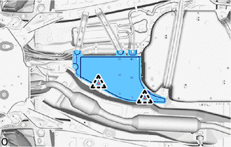
                  26. REMOVE FRONT NO. 2 FLOOR HEAT INSULATOR 


                           | 
                               (a) Remove the 2 nuts, clip and front No. 2 floor heat insulator. 
                            | 
                           
                              
                            | 


                  27. REMOVE FRONT LOWER NO. 1 FLOOR HEAT INSULATOR 


                           | 
                               (a) Remove the nut, bolt, clip and front lower No. 1 floor heat insulator. 
                            | 
                           
                              
                            | 


                  28. REMOVE FRONT NO. 1 FLOOR HEAT INSULATOR 


                           | 
                               (a) Remove the 2 nuts and front No. 1 floor heat insulator. 
                            | 
                           
                              
                            | 


                  29. REMOVE NO. 2 ENGINE SERVICE COVER CUSHION 


                           | 
                               (a) Remove the 2 nuts and No. 2 engine service cover cushion. 
                            | 
                           
                              
                            | 


                  30. REMOVE ENGINE SERVICE COVER CUSHION 


                           | 
                               (a) Remove the 2 nuts and engine service cover cushion. 
                            | 
                           
                              
                            | 


                  31. DISCONNECT TRANSMISSION CONTROL CABLE ASSEMBLY 


                           | 
                               (a) Remove the nut and disconnect the transmission control cable assembly. 
                            | 
                           
                              
                            | 


                  32. REMOVE FRONT EXHAUST PIPE ASSEMBLY 
                  Click here


                  33. REMOVE EXHAUST MANIFOLD 
                  Click here


                  34. REMOVE FUEL TANK ASSEMBLY 
                  Click here


                  35. REMOVE HV FLOOR UNDER WIRE 
                  CAUTION: 
                  Be sure to wear insulated gloves. 
                  NOTICE: 
                  Insulate the disconnected connectors with insulating tape. 
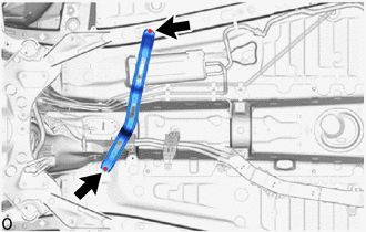


                           | 
                               (b) Disengage the grommet and pull out the HV floor under wire from the floor panel hole. 
                            | 
                           
                              
                            | 


                           | 
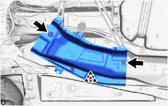
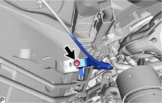
                               (c) Remove the 3 bolts and nut. 
                            | 
                           
                              
                            | 


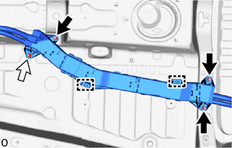
                  (d) Remove the 2 stud clamps. 
                  NOTICE: 
                  If the stud clamps are removed forcibly, the stud bolts may be damaged. 


                           | 
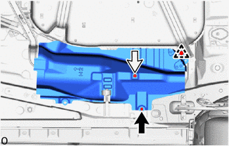
                               (e) Remove the 2 nuts, bolt and 2 stud clamps. 
                              NOTICE: 
                              If the stud clamps is removed forcibly, the stud bolt may be damaged. 
                            | 
                           
                              
                            | 


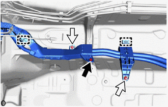
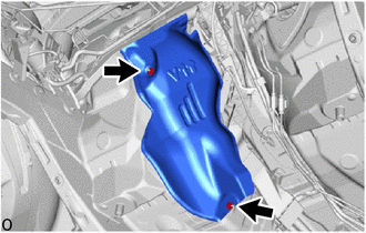
                  (f) Disengage the 2 claws. 


                            | 
                           
                               Remove in this Direction 
                            | 


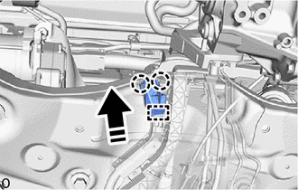
                  (g) Disengage the guide and disconnect the No. 1 terminal cap. 


                           | 
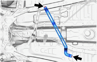
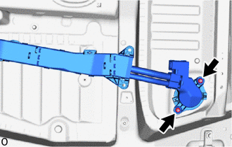
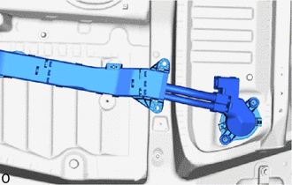
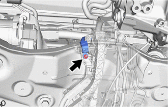
                               (h) Remove the nut and disconnect the engine room main wire. 
                            | 
                           
                              
                            | 


                           | 
                               (i) Remove the 2 nuts and HV floor under wire. 
                            | 
                           
                              
                            | 


                |