| Last Modified: 01-30-2024 | 6.11:8.1.0 | Doc ID: RM100000001FHCR |
| Model Year Start: 2019 | Model: RAV4 | Prod Date Range: [11/2018 - ] |
| Title: AXLE AND DIFFERENTIAL: FRONT AXLE HUB: ON-VEHICLE INSPECTION; 2019 - 2024 MY RAV4 RAV4 HV [11/2018 - ] | ||
ON-VEHICLE INSPECTION
CAUTION / NOTICE / HINT
HINT:
- Use the same procedure for the RH and LH sides.
- The following procedure is for the LH side.
PROCEDURE
1. DISABLE BRAKE CONTROL (w/o Vacuum Brake Booster)
2. REMOVE FRONT WHEEL
3. DISCONNECT FRONT FLEXIBLE HOSE
4. DISCONNECT FRONT DISC BRAKE CALIPER ASSEMBLY LH
5. REMOVE FRONT DISC
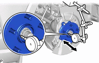
6. INSPECT FRONT AXLE HUB BEARING LOOSENESS
|
(a) Using a dial indicator with magnetic base, check for looseness near the center of the front axle hub sub-assembly. Maximum looseness: 0.05 mm (0.00197 in.) NOTICE:
HINT: If the looseness exceeds the maximum, replace the front axle hub sub-assembly. |
|
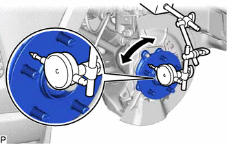
7. INSPECT FRONT AXLE HUB RUNOUT
|
(a) Using a dial indicator with magnetic base, check for runout on the surface of the front axle hub sub-assembly outside the front axle hub bolts. Maximum runout: 0.05 mm (0.00197 in.) NOTICE:
HINT: If the runout exceeds the maximum, replace the front axle hub sub-assembly. |
|
8. INSTALL FRONT DISC
9. INSTALL FRONT DISC BRAKE CALIPER ASSEMBLY LH
10. INSTALL FRONT FLEXIBLE HOSE
11. INSTALL FRONT WHEEL
12. CONNECT CABLE TO NEGATIVE AUXILIARY BATTERY TERMINAL (w/o Vacuum Brake Booster)
(a) Connect the reservoir level switch connector.
(b) Connect the cable to the negative (-) auxiliary battery terminal.
(c) Perform the following procedure if air bleeding is not necessary:
(1) Turn the ignition switch on (READY).
(2) Depress the brake pedal and release it.
(3) Clear the DTCs.
|
|
|
![2019 MY RAV4 RAV4 HV [11/2018 - 02/2019]; BRAKE (REAR): REAR BRAKE: REMOVAL+](/t3Portal/stylegraphics/info.gif)

