| Last Modified: 01-30-2024 | 6.11:8.1.0 | Doc ID: RM100000001FJ42 |
| Model Year Start: 2019 | Model: RAV4 | Prod Date Range: [11/2018 - ] |
| Title: AXLE AND DIFFERENTIAL: REAR DIFFERENTIAL CARRIER ASSEMBLY (for Torque Vectoring Differential): INSTALLATION; 2019 - 2024 MY RAV4 RAV4 HV [11/2018 - ] | ||
INSTALLATION
PROCEDURE
1. INSTALL REAR DIFFERENTIAL SUPPORT
(a) Install the rear differential support to the torque vectoring differential carrier assembly with 3 new bolts.
Torque:
120 N·m {1224 kgf·cm, 89 ft·lbf}
2. INSTALL REAR DIFFERENTIAL DAMPER
(a) Install the rear differential damper to the rear No. 2 differential support with the bolt.
Torque:
20 N·m {204 kgf·cm, 15 ft·lbf}
3. TEMPORARILY INSTALL REAR NO. 2 DIFFERENTIAL SUPPORT
|
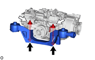
(a) Temporarily install the rear No. 2 differential support to the torque vectoring differential carrier assembly with the 2 bolts and 2 nuts. NOTICE:
HINT: The nuts have tabs to prevent them from rotating. |
|
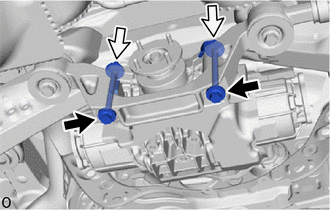
(b) Install the 2 upper rear differential mount stoppers to the rear No. 2 differential support.
4. INSTALL FRAME WIRE
(a) Engage the clamp to install the frame wire.
(b) Connect the 2 connectors and breather tube.
5. INSTALL TORQUE VECTORING DIFFERENTIAL CARRIER ASSEMBLY
NOTICE:
- Do not damage the contact surface when installing the torque vectoring differential carrier assembly.
- Securely support the torque vectoring differential carrier assembly while performing this step to avoid excessively tilting or dropping the torque vectoring differential carrier assembly .
- Install the bolts and nuts with the torque vectoring differential carrier assembly secured.
- Be careful not to damage the frame wire.
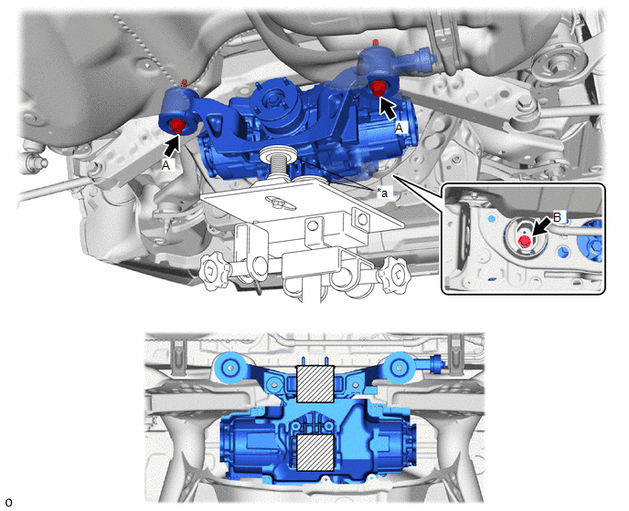
(a) Support the torque vectoring differential carrier assembly with a transmission jack and 2 attachments or equivalent tools as shown in the illustration.
(b) Temporarily install the torque vectoring differential carrier assembly to the rear suspension member sub-assembly with the 2 rear lower differential mount stoppers and 3 new bolts.

|
*a |
Attachment |
- |
- |

|
Attachment Installation Position |
- |
- |
(c) Tighten the 2 bolts (A).
Torque:
86 N·m {877 kgf·cm, 63 ft·lbf}
NOTICE:
Do not tighten the bolts with the inner cylinder or rear differential mount cushion tilted.
(d) Tighten the bolt (B).
Torque:
130 N·m {1326 kgf·cm, 96 ft·lbf}
NOTICE:
Do not tighten the bolts with the inner cylinder or rear differential mount cushion tilted.
(e) w/ Height Control Sensor:
(1) Engage the 7 clamps to install the frame wire.
(f) w/o Height Control Sensor:
(1) Engage the 6 clamps to install the frame wire.
(g) Pass the connector through the hole to the inside of the vehicle and install the grommet of the frame wire.
(h) Connect the 3 connectors.
6. INSTALL DIFFERENTIAL SUPPORT
|
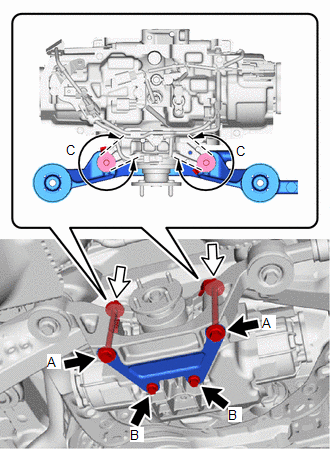
(a) Remove the 2 bolts and 2 nuts. |
|
|
(b) Temporarily install the differential support to the torque vectoring differential carrier assembly with 2 new bolts (A) and 2 new nuts. NOTICE: Be sure to install the tab of each nut to the position (C) shown in the illustration. HINT: The nuts have tabs to prevent them from rotating. |
|
(c) Temporarily install the 2 bolt (B).
(d) Tighten the 4 bolts and 2 nuts.
Torque:
Bolt A :
82 N·m {836 kgf·cm, 60 ft·lbf}
Bolt B :
38.5 N·m {393 kgf·cm, 28 ft·lbf}
7. INSTALL REAR DRIVE SHAFT ASSEMBLY LH
8. INSTALL REAR DRIVE SHAFT ASSEMBLY RH
HINT:
Use the same procedure described for the LH side.
9. INSTALL NO. 1 FUEL TANK PROTECTOR
10. INSTALL REAR STABILIZER BAR
11. INSTALL PROPELLER SHAFT ASSEMBLY
12. INSTALL DECK TRIM SIDE PANEL ASSEMBLY LH
13. INSTALL LUGGAGE HOLD BELT STRIKER ASSEMBLY
14. INSTALL TETHER ANCHOR BRACKET SET
15. INSTALL REAR SEAT SIDE GARNISH LH
16. INSTALL REAR DOOR OPENING TRIM WEATHERSTRIP LH
17. INSTALL REAR DOOR SCUFF PLATE LH
18. INSTALL REAR NO. 1 FLOOR MAT SUPPORT SIDE PLATE
19. INSTALL REAR FLOOR FINISH PLATE
20. INSTALL REAR NO. 3 FLOOR BOARD
21. INSTALL DECK BOARD ASSEMBLY
22. INSTALL TONNEAU COVER ASSEMBLY (w/ Tonneau Cover)
23. INSTALL CHILD RESTRAINT SEAT ANCHOR BRACKET SUB-ASSEMBLY LH
24. INSTALL REAR SEAT ASSEMBLY
25. CONNECT CABLE TO NEGATIVE BATTERY TERMINAL
NOTICE:
When disconnecting the cable, some systems need to be initialized after the cable is reconnected.
26. ADD DIFFERENTIAL OIL
27. DYNAMIC TORQUE VECTORING AWD SYSTEM CALIBRATION
|
|
|


![2019 MY RAV4 RAV4 HV [11/2018 - 10/2019]; DRIVE SHAFT / PROPELLER SHAFT: REAR DRIVE SHAFT ASSEMBLY: INSTALLATION](/t3Portal/stylegraphics/info.gif)