| Last Modified: 05-08-2025 | 6.11:8.1.0 | Doc ID: RM100000001FOYZ |
| Model Year Start: 2019 | Model: RAV4 | Prod Date Range: [11/2018 - ] |
| Title: THEFT DETERRENT / KEYLESS ENTRY: THEFT DETERRENT SYSTEM: Horn Circuit; 2019 - 2025 MY RAV4 RAV4 HV [11/2018 - ] | ||
|
Horn Circuit |
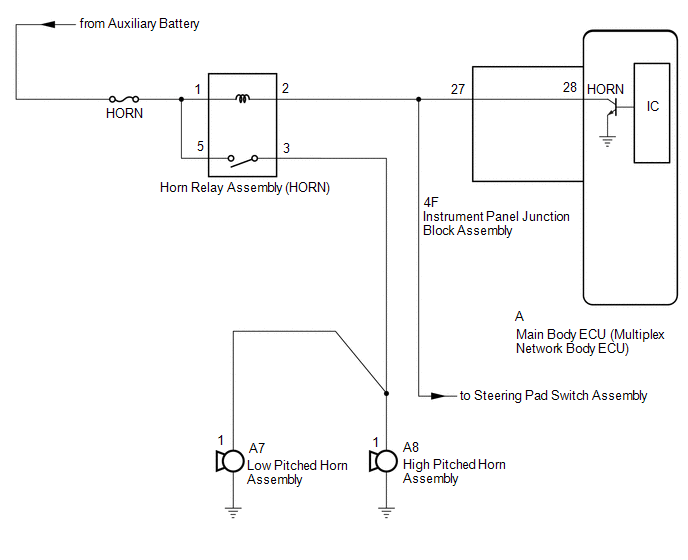
DESCRIPTION
When the theft deterrent system is switched from the armed state to the alarm sounding state, the main body ECU (multiplex network body ECU) transmits a signal to cause the horn to sound at intervals of 0.4 seconds.
WIRING DIAGRAM
CAUTION / NOTICE / HINT
NOTICE:
- Inspect the fuses for circuits related to this system before performing the following inspection procedure.
-
w/ Smart Key System:
If the main body ECU (multiplex network body ECU) is replaced, refer to Registration.
PROCEDURE
|
1. |
CHECK HORNS OPERATION |
(a) Press the horn switch and check if the horns sound.
| Horns do not sound |

|
|

|
2. |
CHECK HARNESS AND CONNECTOR (HORN RELAY ASSEMBLY [HORN] - INSTRUMENT PANEL JUNCTION BLOCK ASSEMBLY) |
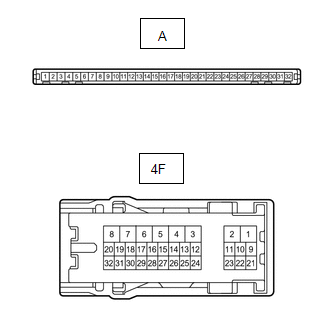
(a) Disconnect the 4F instrument panel junction block assembly connector.
(b) Remove the horn relay assembly (HORN).
(c) Measure the resistance according to the value(s) in the table below.
Standard Resistance:
|
Tester Connection |
Condition |
Specified Condition |
|---|---|---|
|
Horn relay terminal 2 - 4F-27 |
Always |
Below 1 Ω |
| NG |
|
REPAIR OR REPLACE HARNESS OR CONNECTOR |
|
|
3. |
INSPECT INSTRUMENT PANEL JUNCTION BLOCK ASSEMBLY |
(a) Remove the instrument panel junction block assembly.
Click here
![2019 MY RAV4 RAV4 HV [11/2018 - 02/2019]; POWER DISTRIBUTION: MAIN BODY ECU: REMOVAL](/t3Portal/stylegraphics/info.gif)
|
(b) Measure the resistance according to the value(s) in the table below. Standard Resistance:
|
|
| OK |
|
REPLACE MAIN BODY ECU (MULTIPLEX NETWORK BODY ECU)
|
| NG |
|
REPLACE INSTRUMENT PANEL JUNCTION BLOCK ASSEMBLY
|
|
|
|