| Last Modified: 11-18-2025 | 6.11:8.1.0 | Doc ID: RM100000001G235 |
| Model Year Start: 2019 | Model: RAV4 | Prod Date Range: [11/2018 - ] |
| Title: THEFT DETERRENT / KEYLESS ENTRY: IMMOBILISER SYSTEM (for Gasoline Model without Smart Key System): B2784; Antenna Coil Open / Short; 2019 - 2025 MY RAV4 [11/2018 - ] | ||
|
DTC |
B2784 |
Antenna Coil Open / Short |
DESCRIPTION
When an open or short circuit is detected in the antenna coil built into the transponder key coil, the transponder key ECU assembly stores this DTC.
|
DTC No. |
Detection Item |
DTC Detection Condition |
Trouble Area |
Note |
|---|---|---|---|---|
|
B2784 |
Antenna Coil Open / Short |
The antenna coil in the transponder key coil is open/shorted. |
|
DTC Output Confirmation Operation:
|
Vehicle Condition and Fail-safe Operation when Malfunction Detected
|
Vehicle Condition when Malfunction Detected |
Fail-safe Operation when Malfunction Detected |
|---|---|
|
Engine cannot be started |
- |
Related Data List and Active Test
|
DTC No. |
Data List and Active Test |
|---|---|
|
B2784 |
Antenna Coil Status |
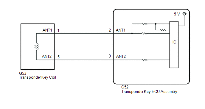
WIRING DIAGRAM
CAUTION / NOTICE / HINT
NOTICE:
-
Before replacing the transponder key ECU assembly, refer to the Registration.
Click here
![2019 - 2022 MY RAV4 [11/2018 - 10/2022]; THEFT DETERRENT / KEYLESS ENTRY: IMMOBILISER SYSTEM (for Gasoline Model without Smart Key System): REGISTRATION](/t3Portal/stylegraphics/info.gif)
- After repair, confirm that no DTCs are output by performing "DTC Output Confirmation Operation".
PROCEDURE
PROCEDURE
|
1. |
CHECK CONNECTION OF CONNECTOR |
(a) Check that the connector is properly connected to the transponder key coil.
|

|
2. |
CLEAR DTC |
(a) Connect the Techstream to the DLC3.
(b) Turn the ignition switch to ON.
(c) Turn the Techstream on.
(d) Enter the following menus: Body Electrical / Immobiliser / Trouble Codes.
(e) Clear the DTCs.
Body Electrical > Immobiliser > Clear DTCs
|
|
3. |
CHECK FOR DTC |
(a) Perform "DTC Output Confirmation Operation" procedure.
(b) Enter the following menus: Body Electrical / Immobiliser / Trouble Codes.
(c) Check for DTCs.
Body Electrical > Immobiliser > Trouble Codes
OK:
DTC B2784 is not output.
|
Result |
Proceed to |
|---|---|
|
B2784 is not output |
A |
|
B2784 is output |
B |
| A |

|
END (CONNECTOR WAS NOT CONNECTED PROPERLY) |
| B |
|
|
4. |
CHECK TRANSPONDER KEY COIL (OUTPUT) |
(a) Disconnect the G53 transponder key coil connector.
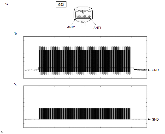
(b) Using an oscilloscope, check the waveform.
|
*a |
Front view of wire harness connector (to Transponder Key Coil) |
*b |
Waveform 1 |
|
*c |
Waveform 2 |
- |
- |
OK
|
Tester Connection |
Condition |
Tool Setting |
Specified Condition |
|---|---|---|---|
|
G53-1 (ANT1) - Body ground |
Within 3 seconds of inserting door control transmitter assembly into ignition key cylinder |
20 V/DIV., 2 s./DIV. |
Pulse generation (See waveform 1) |
|
G53-5 (ANT2) - Body ground |
Within 3 seconds of inserting door control transmitter assembly into ignition key cylinder |
20 V/DIV., 2 s./DIV. |
Pulse generation (See waveform 2) |
OK:
Waveform is similar to that shown in the illustration.
| OK |
|
| NG |
|
|
5. |
CHECK HARNESS AND CONNECTOR (TRANSPONDER KEY ECU ASSEMBLY - TRANSPONDER KEY COIL) |
(a) Disconnect the G52 transponder key ECU assembly connector.
(b) Measure the resistance according to the value(s) in the table below.
Standard Resistance:
|
Tester Connection |
Condition |
Specified Condition |
|---|---|---|
|
G52-2 (ANT1) - G53-1 (ANT1) |
Always |
Below 1 Ω |
|
G52-3 (ANT2) - G53-5 (ANT2) |
Always |
Below 1 Ω |
|
G52-2 (ANT1) or G53-1 (ANT1) - Other terminals and body ground |
Always |
10 kΩ or higher |
|
G52-3 (ANT2) or G53-5 (ANT2) - Other terminals and body ground |
Always |
10 kΩ or higher |
| OK |
|
REPLACE TRANSPONDER KEY ECU ASSEMBLY Click here
|
| NG |
|
REPAIR OR REPLACE HARNESS OR CONNECTOR |
|
|
|