| Last Modified: 11-18-2025 | 6.11:8.1.0 | Doc ID: RM100000001G23A |
| Model Year Start: 2019 | Model: RAV4 | Prod Date Range: [11/2018 - ] |
| Title: THEFT DETERRENT / KEYLESS ENTRY: IMMOBILISER SYSTEM (for Gasoline Model without Smart Key System): B279986; Engine Immobiliser System Signal (Some Circuit Quantity, Reported via Serial Data) Invalid; 2019 - 2025 MY RAV4 [11/2018 - ] | ||
|
DTC |
B279986 |
Engine Immobiliser System Signal (Some Circuit Quantity, Reported via Serial Data) Invalid |
DESCRIPTION
If there is a communication malfunction between the ECM and transponder key ECU assembly, or when the communication ID codes do not match, the ECM stores this DTC.
|
DTC No. |
Detection Item |
DTC Detection Condition |
Trouble Area |
Note |
|---|---|---|---|---|
|
B279986 |
Engine Immobiliser System Signal (Some Circuit Quantity, Reported via Serial Data) Invalid |
One of the following conditions is met:
|
|
DTC Output Confirmation Operation:
|
Vehicle Condition and Fail-safe Operation when Malfunction Detected
|
Vehicle Condition when Malfunction Detected |
Fail-safe Operation when Malfunction Detected |
|---|---|
|
Engine cannot be started |
- |
Related Data List and Active Test
|
DTC No. |
Data List and Active Test |
|---|---|
|
B279986 |
- |
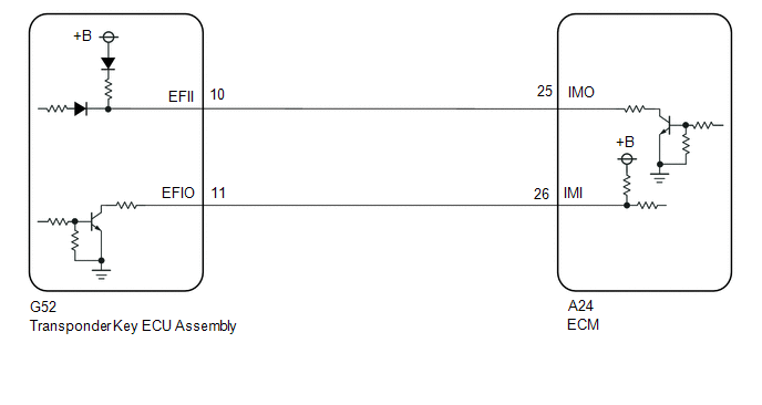
WIRING DIAGRAM
CAUTION / NOTICE / HINT
NOTICE:
-
Before replacing the transponder key ECU assembly or ECM, refer to the Registration.
Click here
![2019 - 2022 MY RAV4 [11/2018 - 10/2022]; THEFT DETERRENT / KEYLESS ENTRY: IMMOBILISER SYSTEM (for Gasoline Model without Smart Key System): REGISTRATION](/t3Portal/stylegraphics/info.gif)
- After repair, confirm that no DTCs are output by performing "DTC Output Confirmation Operation".
HINT:
If transponder key ECU assembly DTCs are output simultaneously, troubleshoot the transponder key ECU assembly DTCs first.
PROCEDURE
PROCEDURE
|
1. |
REGISTER ECU COMMUNICATION ID |
(a) Reregister the ECU communication ID.
Click here
|

|
2. |
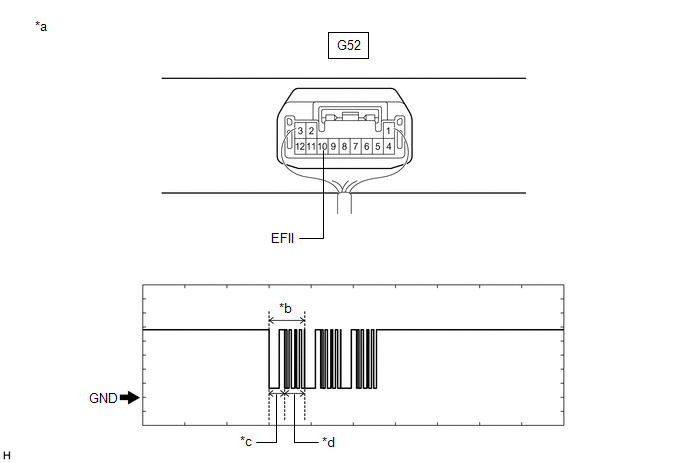
CHECK ECM (TERMINAL EFII) |
(a) Using an oscilloscope, check the waveform.
|
*a |
Component with harness connected (Transponder Key ECU Assembly) |
*b |
Waveform |
|
*c |
Approximately 160 ms. |
*d |
Approximately 270 ms. |
Measurement Condition:
|
Tester Connection |
Condition |
Tool Setting |
Specified Condition |
|---|---|---|---|
|
G52-10 (EFII) - Body ground |
Within 3 seconds of engine start or within 3 seconds of ignition switch turned ON after cable disconnected and reconnected to battery |
2 V/DIV., 500 ms./DIV. |
Pulse generation (See waveform) |
|
Result |
Proceed to |
|---|---|
|
Normal waveform |
A |
|
Terminal EFII stuck low (2.4 V or less) |
B |
|
Waveform length or shape is abnormal, or EFII terminal stuck at Hi (12 V) |
C |
| C |

|
REPLACE ECM Click here
|
| B |
|
|
|
3. |
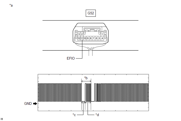
CHECK TRANSPONDER KEY ECU ASSEMBLY (TERMINAL EFIO) |
(a) Using an oscilloscope, check the waveform.
|
*a |
Component with harness connected (Transponder Key ECU Assembly) |
*b |
Waveform |
|
*c |
Approximately 160 ms. |
*d |
Approximately 270 ms. |
Measurement Condition:
|
Tester Connection |
Condition |
Tool Setting |
Specified Condition |
|---|---|---|---|
|
G52-11 (EFIO) - Body ground |
Within 3 seconds of engine start or within 3 seconds of ignition switch turned ON after cable disconnected and reconnected to battery |
2 V/DIV., 500 ms./DIV. |
Pulse generation (See waveform) |
| NG |
|
REPLACE TRANSPONDER KEY ECU ASSEMBLY Click here
|
|
|
4. |
REGISTER ECU COMMUNICATION ID |
(a) Reregister the ECU communication ID.
Click here
|
|
5. |
CHECK WHETHER ENGINE STARTS |
(a) Check that the engine starts.
|
Result |
Proceed to |
|---|---|
|
Engine was started |
A |
|
Engine was not started |
B |
| A |
|
END (ECU COMMUNICATION ID HAS NOT BEEN REGISTERED) |
| B |
|
REPLACE ECM Click here
|
|
6. |
CHECK ECM (TERMINAL IMO) |
|
(a) Disconnect the ECM connector. |
|
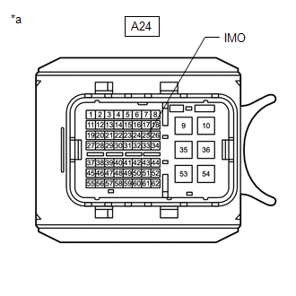
(b) Measure the voltage according to the value(s) in the table below.
Standard Voltage:
|
Tester Connection |
Switch Condition |
Specified Condition |
|---|---|---|
|
A24-25 (IMO) - Body ground |
Ignition switch turned ON using registered electrical key transmitter sub-assembly |
Terminal IMO stuck low (2.4 V or less) |
|
Terminal IMO stuck high (12 V) |
|
Result |
Proceed to |
|---|---|
|
Terminal IMO stuck low (2.4 V or less) |
A |
|
Terminal IMO stuck high (12 V) |
B |
| B |
|
REPLACE ECM Click here
|
|
|
7. |
CHECK HARNESS AND CONNECTOR (TRANSPONDER KEY ECU ASSEMBLY - ECM) |
(a) Disconnect the G52 transponder key ECU assembly connector.
(b) Measure the resistance according to the value(s) in the table below.
Standard Resistance:
|
Tester Connection |
Condition |
Specified Condition |
|---|---|---|
|
G52-10 (EFII) - A24-25 (IMO) |
Always |
Below 1 Ω |
|
G52-10 (EFII) or A24-25 (IMO) - Other terminals and body ground |
Always |
10 kΩ or higher |
| OK |
|
REPLACE TRANSPONDER KEY ECU ASSEMBLY Click here
|
| NG |
|
REPAIR OR REPLACE HARNESS OR CONNECTOR |
|
|
|