| Last Modified: 01-30-2024 | 6.11:8.1.0 | Doc ID: RM100000001H3VN |
| Model Year Start: 2019 | Model: RAV4 HV | Prod Date Range: [02/2019 - 08/2020] |
| Title: P710 (HYBRID TRANSMISSION / TRANSAXLE): COMBINATION SWITCH: INSPECTION; 2019 - 2020 MY RAV4 HV [02/2019 - 08/2020] | ||
INSPECTION
PROCEDURE
1. INSPECT INTEGRATION CONTROL AND PANEL ASSEMBLY (COMBINATION SWITCH)
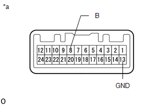
(a) Inspect the NORMAL mode switch:
|
(1) Measure the resistance according to the value(s) in the table below. Standard Resistance:
If the result is not as specified, replace the integration control and panel assembly (combination switch). |
|
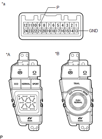
(b) Inspect the SPORT mode switch:
|
(1) Measure the resistance according to the value(s) in the table below. Standard Resistance (for 2WD):
Standard Resistance (for AWD):
If the result is not as specified, replace the integration control and panel assembly (combination switch). |
|
|
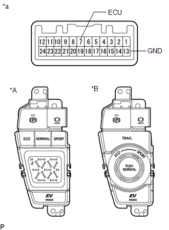
(c) Inspect the ECO mode switch: (1) Measure the resistance according to the value(s) in the table below. Standard Resistance (for 2WD):
Standard Resistance (for AWD):
If the result is not as specified, replace the integration control and panel assembly (combination switch). |
|
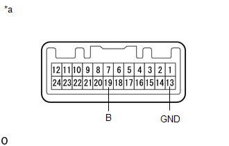
(d) for AWD:
Inspect the TRAIL mode switch:
|
(1) Measure the resistance according to the value(s) in the table below. Standard Resistance:
If the result is not as specified, replace the integration control and panel assembly (combination switch). |
|
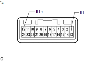
(e) Inspect the illumination:
|
(1) Apply battery voltage to the combination switch and check that the switch illuminates. OK:
If the result is not as specified, replace the integration control and panel assembly (combination switch). |
|
|
|
|