| 
                           Last Modified: 05-08-2025 | 
                        6.11:8.1.0  | 
                        
                           Doc ID: RM100000001HGBB | 
                      
                     
                        | 
                           Model Year Start: 2019 | 
                        
                           Model: RAV4 | 
                        
                           Prod Date Range: [02/2019 - 10/2019] | 
                      
                     
                        | 
                           Title: CELLULAR COMMUNICATION: SAFETY CONNECT SYSTEM: DCM POWER SOURCE CIRCUIT; 2019 MY RAV4 RAV4 HV [02/2019 - 10/2019] | 


                  DESCRIPTION
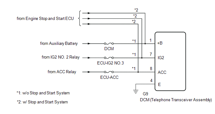
                  This is the power source circuit to operate the DCM (Telephone Transceiver Assembly). 
                   
                  WIRING DIAGRAM
                   
                   
                  CAUTION / NOTICE / HINT
                  NOTICE: 
                  Inspect the fuses for circuits related to this system before performing the following procedure. 
                   
                  PROCEDURE


                           | 
                               1.  
                            | 
                           
                               CHECK HARNESS AND CONNECTOR (DCM (TELEPHONE TRANSCEIVER ASSEMBLY) - BATTERY AND GROUND) 
                            | 


                           | 
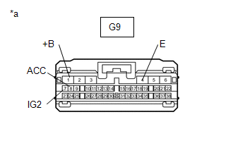
                               (a) Disconnect the DCM (Telephone Transceiver Assembly) connector. 
                            | 


                                     | 


                                                | 
                                                    *a 
                                                 | 
                                                
                                                    Front view of wire harness connector 
                                                   (to DCM (Telephone Transceiver Assembly)) 
                                                 | 


                                     | 
                                  
                               
                            | 


                  (b) Measure the resistance according to the value(s) in the table below. 
                  Standard Resistance:  


                           | 
                               Tester Connection 
                            | 
                           
                               Condition 
                            | 
                           
                               Specified Condition 
                            | 


                           | 
                               G9-4 (E) - Body ground 
                            | 
                           
                               Always 
                            | 
                           
                               Below 1 Ω 
                            | 


                  (c) Measure the voltage according to the value(s) in the table below. 
                  Standard Voltage:  


                           | 
                               Tester Connection 
                            | 
                           
                               Switch Condition 
                            | 
                           
                               Specified Condition 
                            | 


                           | 
                               G9-1 (+B) - G9-4 (E) 
                            | 
                           
                               Ignition switch off 
                            | 
                           
                               11 to 14 V*1 
                              10.5 to 16 V*2 
                            | 
                         
                        
                           | 
                               G9-7 (IG2) - G9-4 (E) 
                            | 
                           
                               Ignition switch ON 
                            | 
                           
                               11 to 14 V*1 
                              10.5 to 16 V*2 
                            | 
                         
                        
                           | 
                               G9-8 (ACC) - G9-4 (E) 
                            | 
                           
                               Ignition switch ACC 
                            | 
                           
                               11 to 14 V*1 
                              10.5 to 16 V*2 
                            | 


                           | NG | 
                           
                               
                            | 
                           
                               REPAIR OR REPLACE HARNESS OR CONNECTOR 
                            | 


                |