| Last Modified: 01-30-2024 | 6.11:8.1.0 | Doc ID: RM100000001HHAI |
| Model Year Start: 2019 | Model: RAV4 | Prod Date Range: [02/2019 - ] |
| Title: DOOR LOCK: KEY REMINDER WARNING SYSTEM: TERMINALS OF ECU; 2019 - 2024 MY RAV4 RAV4 HV [02/2019 - ] | ||
TERMINALS OF ECU
CHECK INSTRUMENT PANEL JUNCTION BLOCK ASSEMBLY AND MAIN BODY ECU (MULTIPLEX NETWORK BODY ECU)
|
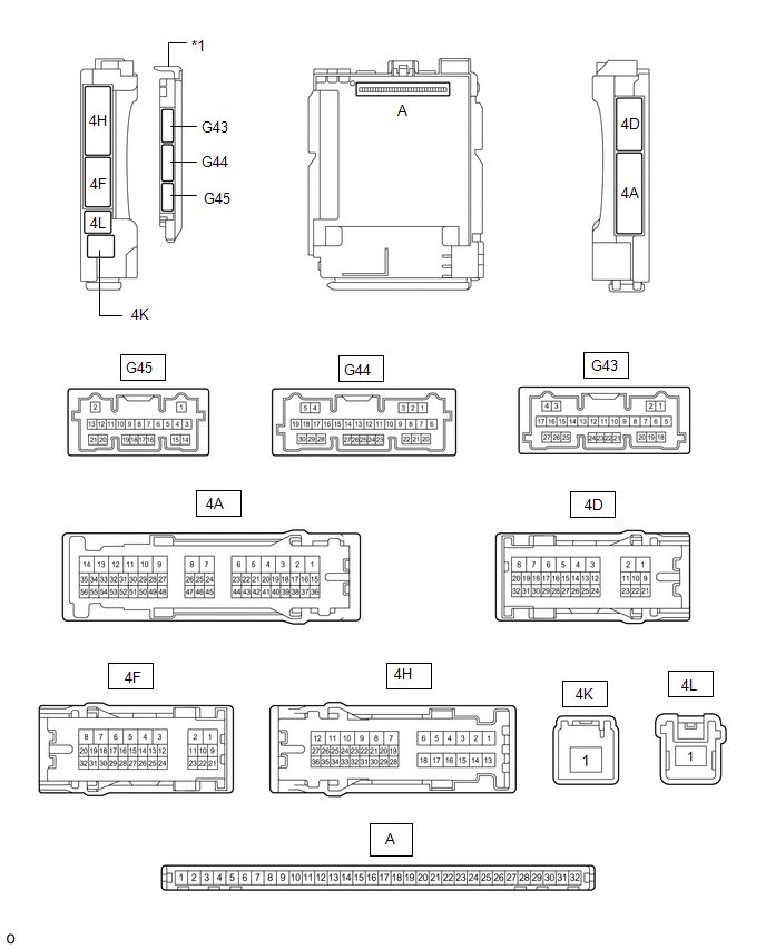
*1 |
Main body ECU (multiplex network body ECU) |
- |
- |
(a) Remove the main body ECU (multiplex network body ECU) from the instrument panel junction block assembly.
Click here
![2019 MY RAV4 RAV4 HV [02/2019 - 10/2019]; POWER DISTRIBUTION: MAIN BODY ECU: REMOVAL](/t3Portal/stylegraphics/info.gif)
(b) Reconnect the instrument panel junction block assembly connectors.
(c) Measure the voltage and resistance according to the value(s) in the table below.
|
Tester Connection |
Wiring Color |
Input/Output |
Terminal Description |
Condition |
Specified Condition |
Related Data List Item |
|---|---|---|---|---|---|---|
|
A-11 (GND1) - Body ground |
- |
- |
Ground |
Always |
Below 1 Ω |
- |
|
A-30 (ACC) - Body ground |
- |
Input |
ACC power supply |
Ignition switch ACC |
11 to 14 V |
ACC SW |
|
Ignition switch off |
Below 1 V |
|||||
|
A-31 (BECU) - Body ground |
- |
Input |
Auxiliary battery power supply |
Ignition switch off |
11 to 14 V |
- |
|
A-32 (IG) - Body ground |
- |
Input |
IG power supply |
Ignition switch ON |
11 to 14 V |
IG SW |
|
Ignition switch off |
Below 1 V |
(d) Install the main body ECU (multiplex network body ECU) to the instrument panel junction block assembly.
Click here
(e) Measure the voltage according to the value(s) in the table below.
|
Terminal No. (Symbol) |
Wiring Color |
Input/Output |
Terminal Description |
Condition |
Specified Condition |
Related Data List Item |
|---|---|---|---|---|---|---|
|
G43-1 (FLCY) - Body ground |
R - Body ground |
Input |
Front door courtesy light switch LH input |
Front door LH open → closed |
Below 1 V → 4.7 to 5.3 V |
FL Door Courtesy SW |
|
4A-41 (KSW) - Body ground |
GR - Body ground |
Input |
Un-lock warning switch input |
No key in ignition key cylinder → Key in ignition key cylinder |
11 to 14 V → Below 1 V |
Key Unlock Warning SW |
|
|
|