- Perform initialization and calibration of the linear solenoid valve
- Perform yaw rate and acceleration sensor zero point calibration
| Last Modified: 05-08-2025 | 6.11:8.1.0 | Doc ID: RM100000001HIKH |
| Model Year Start: 2019 | Model: RAV4 | Prod Date Range: [02/2019 - 10/2019] |
| Title: BRAKE SYSTEM (OTHER): BRAKE BOOSTER (w/o Vacuum Brake Booster): REMOVAL; 2019 MY RAV4 RAV4 HV [02/2019 - 10/2019] | ||
REMOVAL
CAUTION / NOTICE / HINT
The necessary procedures (adjustment, calibration, initialization or registration) that must be performed after parts are removed and installed, or replaced during brake booster with master cylinder assembly removal/installation are shown below.
Necessary Procedures After Parts Removed/Installed/Replaced (for HV Model)
|
Replaced Part or Performed Procedure |
Necessary Procedure |
Effect/Inoperative Function when Necessary Procedure not Performed |
Link |
|---|---|---|---|
|
*: When performing learning using the Techstream.
Click here
|
|||
|
Auxiliary battery terminal is disconnected/reconnected |
Perform steering sensor zero point calibration |
Lane control system |
|
|
Parking support brake system (for HV model)* |
|||
|
Pre-collision system |
|||
|
Lighting system (EXT)(w/ AFS) |
|||
|
Memorize steering angle neutral point |
Parking assist monitor system |
|
|
|
Panoramic view monitor system (for HV model) |
|
||
|
Reset back door close position |
Power back door system (for HV model) |
|
|
|
Back door lock initialization |
Power door lock control system |
|
|
|
Replacement of brake booster with master cylinder assembly |
|
|
|
NOTICE:
- After the ignition switch is turned off, the radio and display receiver assembly records various types of memory and settings. As a result, after turning the ignition switch off, be sure to wait for the time specified in the following table before disconnecting the cable from the negative (-) auxiliary battery terminal.
- While the auxiliary battery is connected, even if the power switch is off, the brake control system activates when the brake pedal is depressed or any door courtesy switch turns on. Therefore, when servicing the brake system components, do not operate the brake pedal or open/close the doors while the auxiliary battery is connected.
Waiting Time before Disconnecting Cable from Negative (-) Auxiliary Battery Terminal
|
System Name |
See Procedure |
|---|---|
|
Vehicle enrolled in Toyota Entune system or safety connect system |
6 minutes |
|
Vehicle not enrolled in Toyota Entune system and safety connect system |
1 minute |
PROCEDURE
1. PRECAUTION
CAUTION:
Be sure to read precaution thoroughly before servicing.
-
w/ Occupant Classification System:
Click here
![2019 - 2020 MY RAV4 RAV4 HV [02/2019 - 08/2020]; SUPPLEMENTAL RESTRAINT SYSTEMS: AIRBAG SYSTEM (w/ Occupant Classification System): PRECAUTION](/t3Portal/stylegraphics/info.gif)
-
w/o Occupant Classification System:
Click here
NOTICE:
After turning the ignition switch off, waiting time may be required before disconnecting the cable from the negative (-) auxiliary battery terminal. Therefore, make sure to read the disconnecting the cable from the negative (-) auxiliary battery terminal notices before proceeding with work.
Click here
2. DISABLE BRAKE CONTROL
Click here
3. REMOVE WINDSHIELD WIPER MOTOR AND LINK ASSEMBLY
Click here
4. REMOVE COWL VENTILATOR PANEL SUB-ASSEMBLY
Click here
5. DRAIN BRAKE FLUID
NOTICE:
If brake fluid leaks onto any painted surface, immediately wash it off.
6. REMOVE LOWER NO. 1 INSTRUMENT PANEL AIRBAG ASSEMBLY
Click here
7. REMOVE NO. 1 AIR DUCT (for TMC Made)
Click here
8. REMOVE NO. 2 AIR DUCT SUB-ASSEMBLY (for TMMC Made)
Click here
9. REMOVE STOP LIGHT SWITCH ASSEMBLY
Click here
10. REMOVE BRAKE PEDAL RETURN SPRING
Click here
11. SEPARATE WIRE HARNESS
|
(a) Disconnect the connector from the brake pedal stroke sensor assembly. |
|
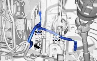
(b) Disengage the 2 clamps to separate the wire harness from the brake pedal support assembly.
12. REMOVE PUSH ROD PIN
Click here
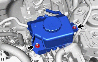
13. SEPARATE BRAKE MASTER CYLINDER RESERVOIR ASSEMBLY
|
(a) Remove the 2 nuts and separate the brake master cylinder reservoir assembly. |
|
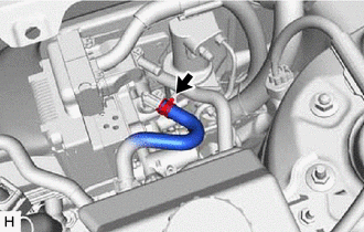
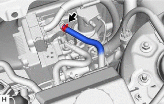
14. DISCONNECT NO. 2 RESERVOIR HOSE
|
(a) Slide the clip and disconnect the No. 2 reservoir hose from the brake booster with master cylinder assembly. |
|
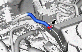
15. DISCONNECT NO. 1 RESERVOIR HOSE
|
(a) Slide the clip and disconnect the No. 1 reservoir hose from the brake booster with master cylinder assembly. |
|
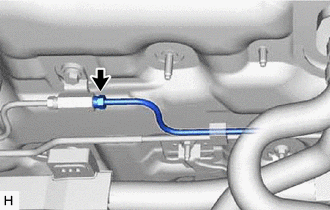
16. DISCONNECT NO. 1 BRAKE ACTUATOR HOSE
|
(a) Slide the clip and disconnect the brake actuator hose from the brake master cylinder reservoir assembly. |
|
17. REMOVE BRAKE MASTER CYLINDER RESERVOIR WITH RESERVOIR HOSE
(a) Remove the brake master cylinder reservoir with reservoir hose
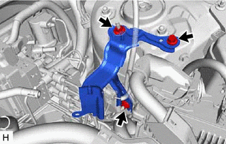
18. REMOVE RESERVOIR BRACKET
|
(a) Remove the bolt, 2 nuts and reservoir bracket. |
|
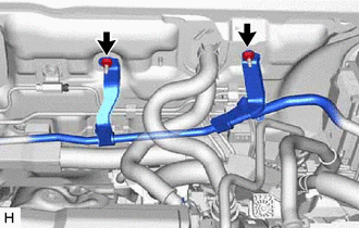
19. SEPARATE NO. 1 BRAKE ACTUATOR TUBE
|
(a) Remove the 2 nuts and separate the No. 1 brake actuator tube from the vehicle body. |
|
20. DISCONNECT NO. 4 FRONT BRAKE TUBE
|
(a) Using a union nut wrench, disconnect the No. 4 front brake tube. NOTICE:
|
|
21. REMOVE BRAKE BOOSTER WITH MASTER CYLINDER ASSEMBLY
(a) Disengage the clamp to separate the wire harness.
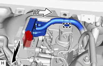

|
Release the lock lever |

|
Disconnect the connector |
(b) Release the lock lever and disconnect the connector from the brake booster with master cylinder assembly.
NOTICE:
Be careful not to allow brake fluid to enter the removed connector.
|
(c) Using a union nut wrench, disconnect the 5 brake lines from the brake booster with master cylinder assembly. |
|
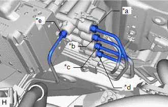
(d) Use tags or make a memo to identify the places to reconnect.
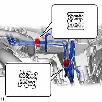
|
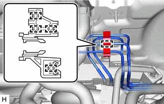
(e) Disengage the 8 clamps to remove the 2 brake tube clamps from the brake lines. |
|
|
(f) Disengage the 4 clamps to remove the brake tube clamp from the brake lines. |
|
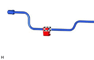
(g) Disengage the clamp and remove the brake tube clamp from the vehicle body.
|
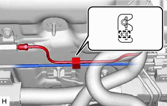
(h) Disengage the clamp to remove the No. 4 front brake tube with brake tube clamp from the brake line. |
|
|
(i) Disengage the clamp to remove the brake tube clamp from the No. 4 front brake tube. |
|
|
(j) Remove the 4 nuts and brake booster with master cylinder assembly. NOTICE:
|
|
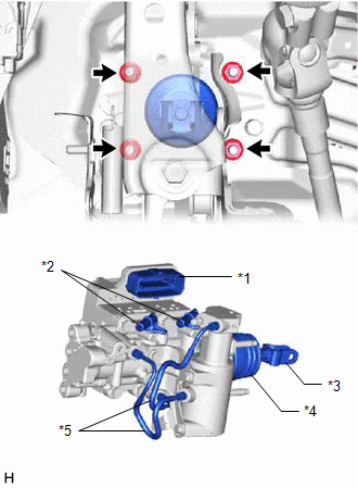
22. REMOVE BRAKE BOOSTER GASKET
|
|
|