| Last Modified: 01-30-2024 | 6.11:8.1.0 | Doc ID: RM100000001K1AD |
| Model Year Start: 2020 | Model: RAV4 | Prod Date Range: [10/2019 - 01/2020] |
| Title: UB80E (AUTOMATIC TRANSMISSION / TRANSAXLE): TRANSMISSION WIRE: REMOVAL; 2020 MY RAV4 [10/2019 - 01/2020] | ||
REMOVAL
CAUTION / NOTICE / HINT
The necessary procedures (adjustment, calibration, initialization or registration) that must be performed after parts are removed and installed, or replaced during transmission wire removal/installation are shown below.
Necessary Procedure After Parts Removed/Installed/Replaced
|
Replaced Part or Performed Procedure |
Necessary Procedure |
Effect/Inoperative Function when Necessary Procedure not Performed |
Link |
|---|---|---|---|
| *: When performing learning using the Techstream. | |||
|
Battery terminal is disconnected/reconnected |
Drive the vehicle until stop and start control is permitted (approximately 5 to 60 minutes) |
Stop and start system |
|
|
Perform steering sensor zero point calibration |
Lane control system |
||
|
Parking support brake system (for Gasoline model)* |
|||
|
Pre-collision system |
|||
|
Memorize steering angle neutral point |
Parking assist monitor system |
||
|
Panoramic view monitor system (for Gasoline model) |
|||
|
Reset back door close position |
Power back door system (for Gasoline model) |
||
|
Back door lock initialization |
Power door lock control system |
||
NOTICE:
After the ignition switch is turned off, the radio and display receiver assembly records various types of memory and settings. As a result, after turning the ignition switch off, be sure to wait for the time specified in the following table before disconnecting the cable from the negative (-) battery terminal.
Waiting Time before Disconnecting Cable from Negative (-) Battery Terminal
|
System Name |
See Procedure |
|---|---|
|
Vehicle enrolled in Toyota Audio Multimedia system or safety connect system |
6 minutes |
|
Vehicle not enrolled in Toyota Audio Multimedia system and safety connect system |
1 minute |
PROCEDURE
1. REMOVE FRONT FENDER FRONT SPLASH SHIELD LH
2. REMOVE FRONT FENDER FRONT SPLASH SHIELD RH
3. REMOVE NO. 1 ENGINE UNDER COVER
4. REMOVE NO. 2 ENGINE UNDER COVER ASSEMBLY
5. REMOVE FRONT FENDER APRON SEAL LH
6. DRAIN AUTOMATIC TRANSAXLE FLUID
|
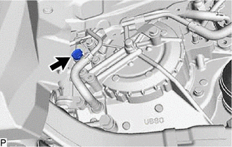
(a) Remove the refill plug and gasket from the automatic transaxle case sub-assembly. |
|
|
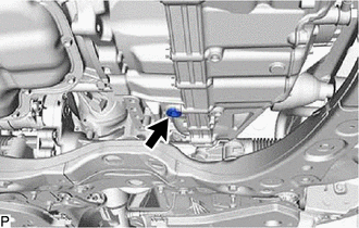
(b) Using a 10 mm hexagon socket wrench, remove the overflow plug and gasket from the transaxle housing. |
|
|
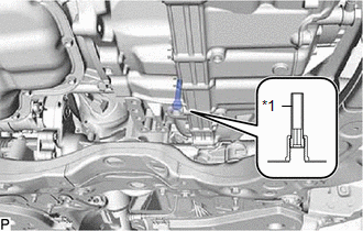
(c) Using a 6 mm hexagon socket wrench, remove the No. 1 transmission oil filler tube from the transaxle housing and drain the automatic transaxle fluid. |
|
(d) Using a 6 mm hexagon socket wrench, install the No. 1 transmission oil filler tube to the transaxle housing.
Torque:
1.7 N·m {17 kgf·cm, 15 in·lbf}
(e) Using a 10 mm hexagon socket wrench, temporarily install the gasket and overflow plug to the transaxle housing.
HINT:
Reuse the old gasket as the overflow plug will be removed again to adjust the automatic transaxle fluid level.
(f) Temporarily install the gasket and refill plug to avoid automatic transaxle fluid spillage.
HINT:
Reuse the old gasket as the refill plug will be removed again to adjust the automatic transaxle fluid level.
7. REMOVE VACUUM SWITCHING VALVE (for Active Control Engine Mount System)
8. REMOVE FRONT ENGINE MOUNTING INSULATOR
9. SEPARATE OIL COOLER UNION SUB-ASSEMBLY
|
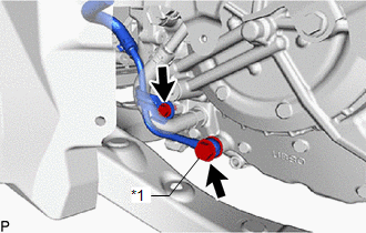
(a) Remove the bolt to separate the oil cooler union sub-assembly bracket portion from the automatic transaxle case sub-assembly. |
|
(b) Remove the oil cooler union bolt and 2 gaskets to separate the oil cooler union sub-assembly from the automatic transaxle case sub-assembly.
10. REMOVE TRANSMISSION CASE SIDE COVER
|
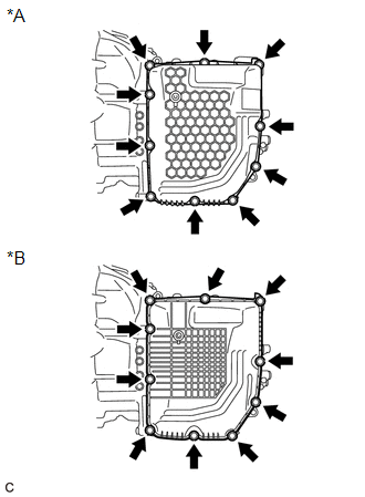
(a) Remove the 10 bolts and transmission case side cover from the automatic transaxle case sub-assembly. |
|
11. REMOVE TRANSMISSION WIRE (w/o Stop And Start System)
|
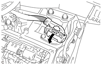
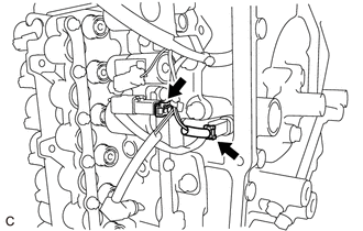
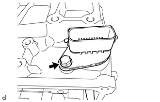
(a) Disengage the claw, rotate the lever and disconnect the transmission wire connector. |
|
|
(b) Disengage the clamp to disconnect the transmission wire from the solenoid lock plate. |
|
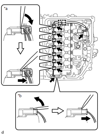
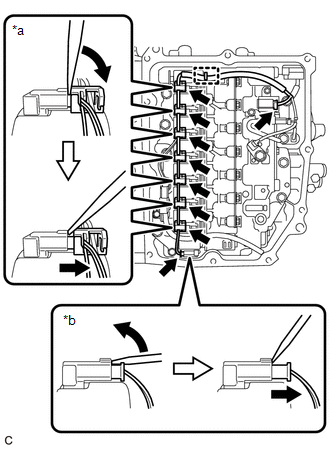
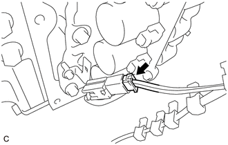
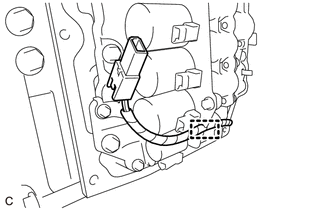
(c) Disconnect the 9 solenoid valve connectors.
HINT:
- Using a screwdriver, disconnect the solenoid valve connector (A) using the procedure shown in the illustration.
- Using a screwdriver, disconnect the solenoid valve connector (B) using the procedure shown in the illustration.
|
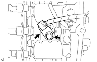
(d) Remove the bolt and temperature sensor clamp and disconnect the temperature sensor from the transmission valve body assembly. |
|
|
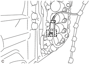
(e) Disconnect the transmission revolution sensor (NT) connector and transmission revolution sensor (NC) connector. |
|
|
(f) Remove the bolt and transmission wire from the automatic transaxle case sub-assembly. |
|
12. REMOVE TRANSMISSION WIRE (w/ Stop And Start System)
|
(a) Disengage the claw, rotate the lever and disconnect the transmission wire connector. |
|
|
(b) Disengage the clamp to disconnect the transmission wire from the solenoid lock plate. |
|
(c) Disconnect the 9 solenoid valve connectors.
HINT:
- Using a screwdriver, disconnect the solenoid valve connector (A) using the procedure shown in the illustration.
- Using a screwdriver, disconnect the solenoid valve connector (B) using the procedure shown in the illustration.
|
(d) Disengage the wire harness clamp to disconnect the transmission wire (oil pump with solenoid assembly). |
|
|
(e) Disconnect the transmission wire connector. |
|
|
(f) Disengage the clamp to disconnect the transmission wire (oil pump with solenoid assembly) from the solenoid lock plate. |
|
|
(g) Remove the bolt and temperature sensor clamp and disconnect the temperature sensor from the transmission valve body assembly. |
|
|
(h) Disconnect the transmission revolution sensor (NT) connector and transmission revolution sensor (NC) connector. |
|
|
(i) Remove the bolt and transmission wire from the automatic transaxle case sub-assembly. |
|
|
|
|
![2019 - 2022 MY RAV4 [11/2018 - 10/2022]; PARK ASSIST / MONITORING: PARKING SUPPORT BRAKE SYSTEM (for Gasoline Model): CALIBRATION](/t3Portal/stylegraphics/info.gif)
