| 
                           Last Modified: 05-08-2025 | 
                        6.11:8.1.0  | 
                        
                           Doc ID: RM100000001OBCV | 
                      
                     
                        | 
                           Model Year Start: 2020 | 
                        
                           Model: RAV4 HV | 
                        
                           Prod Date Range: [06/2020 -                    
                                       ] | 
                      
                     
                        | 
                           Title: HYBRID / BATTERY CONTROL: HYBRID CONTROL SYSTEM (for LITHIUM-ION BATTERY): P0A361C,P0A361F; Generator Temperature Sensor Voltage Out of Range; 2020 - 2025 MY RAV4 HV [06/2020 -        ] | 


                           | 
                               DTC 
                            | 
                           
                               P0A361C 
                            | 
                           
                               Generator Temperature Sensor Voltage Out of Range 
                            | 


                           | 
                               DTC 
                            | 
                           
                               P0A361F 
                            | 
                           
                               Generator Temperature Sensor Circuit Intermittent 
                            | 


                  DTC SUMMARY
                  MALFUNCTION DESCRIPTION 
                  These DTCs are stored when the generator temperature sensor output is abnormal. The cause of this malfunction may be one of the following: 
                  
                     Hybrid vehicle control ECU assembly malfunction
                     
                        - 
Hybrid vehicle control ECU assembly internal malfunction


                     Generator temperature sensor malfunction
                     
                        - 
Internal generator temperature sensor malfunction
 
                        - 
Open or short in generator temperature sensor


                     Wire harness between the generator temperature sensor and hybrid vehicle control ECU assembly
                     
                        - 
The connectors are not connected properly
 
                        - 
Foreign matter or water on the connector terminals
 
                        - 
Open or short in wire harness


                  HINT: 
                  If any of these DTCs are stored, the generator temperature sensor is malfunctioning and the self-protection function may not operate. Therefore under certain high load driving condition, the temperature of the generator (MG1) becomes high. If the self-protection function does not operate, the generator (MG1) may malfunction and cause the vehicle to enter fail-safe mode. 
                   
                  DESCRIPTION
                  Refer to the description for DTC P0A3611. 
                  Click here


                           | 
                               DTC No. 
                            | 
                           
                               Detection Item 
                            | 
                           
                               DTC Detection Condition 
                            | 
                           
                               Trouble Area 
                            | 
                           
                               MIL 
                            | 
                           
                               Warning Indicate 
                            | 


                           | 
                               P0A361C 
                            | 
                           
                               Generator Temperature Sensor Voltage Out of Range 
                            | 
                           
                               After a long soak, the value of the generator (MG1) temperature sensor is different from the value of the other temperature sensors. 
                              (2 trip detection logic) 
                            | 


                                    - 
Wire harness or connector
 
                                    - 
Generator temperature sensor (Hybrid vehicle transaxle assembly)


                            | 
                           
                               Comes on 
                            | 
                           
                               Master Warning: 
                              Comes on 
                            | 
                         
                        
                           | 
                               P0A361F 
                            | 
                           
                               Generator Temperature Sensor Circuit Intermittent 
                            | 
                           
                               Sudden change in generator temperature sensor output or hunting: 
                              Unusual sudden change in generator temperature sensor output occurs and offset condition continues for a certain period of time, or unusual change in motor temperature sensor output occurs repeatedly. 
                              (1 trip detection logic) 
                            | 


                                    - 
Wire harness or connector
 
                                    - 
Generator temperature sensor (Hybrid vehicle transaxle assembly)


                            | 
                           
                               Comes on 
                            | 
                           
                               Master Warning: 
                              Comes on 
                            | 


                  Related Data List


                           | 
                               DTC No. 
                            | 
                           
                               Data List 
                            | 


                           | 
                               P0A361C 
                            | 


                                    - 
Generator Temperature
 
                                    - 
Motor Temperature
 
                                    - 
Inverter Coolant Water Temperature


                            | 
                         
                        
                           | 
                               P0A361F 
                            | 
                           
                               Generator Temperature 
                            | 


                  MONITOR DESCRIPTION
                  If the hybrid vehicle control ECU assembly detects a malfunction of the generator temperature sensor, it will illuminate the MIL and store a DTC. 
                   
                  MONITOR STRATEGY


                           | 
                               Related DTCs 
                            | 
                           
                               P0A37 (INF P0A361C): Generator Temperature Sensor Circuit Range/Performance 
                              P0A3A (INF P0A361F): Generator Temperature Sensor Circuit Intermittent 
                            | 
                         
                        
                           | 
                               Required sensors/components 
                            | 
                           
                               Generator temperature sensor 
                            | 
                         
                        
                           | 
                               Frequency of operation 
                            | 
                           
                               Continuous 
                            | 
                         
                        
                           | 
                               Duration 
                            | 
                           
                               TMC's intellectual property 
                            | 
                         
                        
                           | 
                               MIL operation 
                            | 
                           
                               2 driving cycle / 1 driving cycle 
                            | 
                         
                        
                           | 
                               Sequence of operation 
                            | 
                           
                               None 
                            | 


                  TYPICAL ENABLING CONDITIONS


                           | 
                               The monitor will run whenever the following DTCs are not stored 
                            | 
                           
                               TMC's intellectual property 
                            | 
                         
                        
                           | 
                               Other conditions belong to TMC's intellectual property 
                            | 
                           
                               - 
                            | 


                  TYPICAL MALFUNCTION THRESHOLDS


                           | 
                               TMC's intellectual property 
                            | 
                           
                               - 
                            | 


                  COMPONENT OPERATING RANGE


                           | 
                               Hybrid vehicle control ECU assembly 
                            | 
                           
                               DTC P0A37 (INF P0A361C) is not detected 
                              DTC P0A3A (INF P0A361F) is not detected 
                            | 


                  CONFIRMATION DRIVING PATTERN
                  
                     HINT: 
                     
                        - 
After repair has been completed, clear the DTC and then check that the vehicle has returned to normal by performing the following All Readiness check procedure.
Click here


                        - 
When clearing the permanent DTCs, refer to the "CLEAR PERMANENT DTC" procedure.
Click here


                     DTC P0A361C
                     
                        - 
Connect the Techstream to the DLC3.
 
                        - 
Turn the ignition switch to ON and turn the Techstream on.
 
                        - 
Clear the DTCs (even if no DTCs are stored, perform the clear DTC procedure).
 
                        - 
Turn the ignition switch off.
 
                        - 
Leave the vehicle as is for 5 hours or more and then check the values of the Data List items "Generator Temperature", "Motor Temperature" and "Inverter Coolant Water Temperature". [*1]
 
                        - 
Turn the ignition switch to ON and turn the Techstream on. [*2]
HINT: 
                           [*1] to [*2]: Normal judgment procedure. 
                           The normal judgment procedure is used to complete DTC judgment and also used when clearing permanent DTCs. 
                         
                        - 
Enter the following menus: Powertrain / Hybrid Control / Utility / All Readiness.
 
                        - 
Check the DTC judgment result.
                              HINT: 
                              
                                 - 
If the judgment result shows NORMAL, the system is normal.
 
                                 - 
If the judgment result shows ABNORMAL, the system has a malfunction.
 
                                 - 
If the judgment result shows INCOMPLETE, perform the normal judgment procedure again.


                     DTC P0A361F
                     
                        - 
Connect the Techstream to the DLC3.
 
                        - 
Turn the ignition switch to ON and turn the Techstream on.
 
                        - 
Clear the DTCs (even if no DTCs are stored, perform the clear DTC procedure).
 
                        - 
Turn the ignition switch off and wait for 2 minutes or more.
 
                        - 
Turn the ignition switch to ON and turn the Techstream on.
 
                        - 
With ignition switch ON and wait for 5 seconds or more. [*1]
HINT: 
                           [*1]: Normal judgment procedure. 
                           The normal judgment procedure is used to complete DTC judgment and also used when clearing permanent DTCs. 
                         
                        - 
Enter the following menus: Powertrain / Hybrid Control / Utility / All Readiness.
 
                        - 
Check the DTC judgment result.
                              HINT: 
                              
                                 - 
If the judgment result shows NORMAL, the system is normal.
 
                                 - 
If the judgment result shows ABNORMAL, the system has a malfunction.
 
                                 - 
If the judgment result shows INCOMPLETE, perform the normal judgment procedure again.


                  WIRING DIAGRAM
                  Refer to the wiring diagram for DTC P0A3611. 
                  Click here


                  PROCEDURE


                           | 
                               1.  
                            | 
                           
                               CHECK DTC OUTPUT (ENGINE) 
                            | 


                  (a) Connect the Techstream to the DLC3. 
                  (b) Turn the ignition switch to ON. 
                  (c) Enter the following menus: Powertrain / Engine / Trouble Codes. 
                  (d) Check for DTCs. 
                  Powertrain > Engine > Trouble Codes


                           | 
                               Result 
                            | 
                           
                               Proceed to 
                            | 


                           | 
                               No DTCs are output, or DTCs except the ones in the table below are also output. 
                            | 
                           
                               A 
                            | 
                         
                        
                           | 
                               Any of the following DTCs are also output. 
                            | 
                           
                               B 
                            | 


                           | 
                               Relevant DTC 
                            | 


                           | 
                               P261029 
                            | 
                           
                               ECM/PCM Engine Off Timer Performance Signal Invalid 
                            | 


                  (e) Turn the ignition switch off. 


                                 | 
A
 | 


                                  | 
                               
                            
                         | 


                           | 
                               2.  
                            | 
                           
                               CHECK DTC OUTPUT (HYBRID CONTROL) 
                            | 


                  (a) Check for DTCs. 
                  Powertrain > Hybrid Control > Trouble Codes


                           | 
                               Result 
                            | 
                           
                               Proceed to 
                            | 


                           | 
                               No DTCs are output, or DTCs except the ones in the table below are also output. 
                            | 
                           
                               A 
                            | 
                         
                        
                           | 
                               Any of the following DTCs are also output. 
                            | 
                           
                               B 
                            | 


                           | 
                               Relevant DTC 
                            | 


                           | 
                               P0A3611 
                            | 
                           
                               Generator Temperature Sensor Circuit Short to Ground 
                            | 
                         
                        
                           | 
                               P0A3615 
                            | 
                           
                               Generator Temperature Sensor Circuit Short to Auxiliary Battery or Open 
                            | 


                  (b) Turn the ignition switch off. 


                                 | 
A
 | 


                                  | 
                               
                            
                         | 


                           | 
                               3.  
                            | 
                           
                               CHECK CONNECTOR CONNECTION CONDITION (HYBRID VEHICLE CONTROL ECU ASSEMBLY CONNECTOR) 
                            | 


                  Click here


                           | 
                               Result 
                            | 
                           
                               Proceed to 
                            | 


                           | 
                               OK 
                            | 
                           
                               A 
                            | 
                         
                        
                           | 
                               NG (The connector is not connected securely.) 
                            | 
                           
                               B 
                            | 
                         
                        
                           | 
                               NG (The terminals are not making secure contact or are deformed, or water or foreign matter exists in the connector.) 
                            | 
                           
                               C 
                            | 


                           | B | 
                           
                               
                            | 
                           
                               CONNECT SECURELY 
                            | 


                           | C | 
                           
                               
                            | 
                           
                               REPAIR OR REPLACE HARNESS OR CONNECTOR 
                            | 


                                 | 
A
 | 


                                  | 
                               
                            
                         | 


                           | 
                               4.  
                            | 
                           
                               INSPECT HYBRID VEHICLE TRANSAXLE ASSEMBLY (GENERATOR TEMPERATURE SENSOR) 
                            | 


                  (a) Disconnect the A29 hybrid vehicle control ECU assembly connector. 


                           | 
                               (b) Measure the resistance according to the value(s) in the table below. 
                              Standard Resistance:  


                                       | 
                                           Tester Connection 
                                        | 
                                       
                                           Condition 
                                        | 
                                       
                                           Specified Condition 
                                        | 


                                       | 
                                           A29-48 (GMT) - A29-47 (GMTG) 
                                        | 
                                       
                                           Ignition switch off 
                                        | 
                                       
                                           0.3338 to 1487 kΩ 
                                        | 


                            | 


                                     | 


                                                | 
                                                    *a 
                                                 | 
                                                
                                                    Front view of wire harness connector 
                                                   (to Hybrid Vehicle Control ECU Assembly) 
                                                 | 


                                     | 
                                  
                               
                            | 


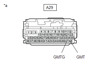
                  (c) Reconnect the A29 hybrid vehicle control ECU assembly connector. 


                                 | 
OK
 | 


                                  | 
                               
                            
                         | 


                           | 
                               5.  
                            | 
                           
                               CHECK CONNECTOR CONNECTION CONDITION (NO. 1 ENGINE ROOM RELAY BLOCK AND JUNCTION BLOCK ASSEMBLY CA3 CONNECTOR) 
                            | 


                  Click here


                           | 
                               Result 
                            | 
                           
                               Proceed to 
                            | 


                           | 
                               OK 
                            | 
                           
                               A 
                            | 
                         
                        
                           | 
                               NG (The connector is not connected securely.) 
                            | 
                           
                               B 
                            | 
                         
                        
                           | 
                               NG (The terminals are not making secure contact or are deformed, or water or foreign matter exists in the connector.) 
                            | 
                           
                               C 
                            | 


                           | B | 
                           
                               
                            | 
                           
                               CONNECT SECURELY 
                            | 


                           | C | 
                           
                               
                            | 
                           
                               REPAIR OR REPLACE HARNESS OR CONNECTOR 
                            | 


                                 | 
A
 | 


                                  | 
                               
                            
                         | 


                           | 
                               6.  
                            | 
                           
                               CHECK HARNESS AND CONNECTOR (HYBRID VEHICLE CONTROL ECU ASSEMBLY - NO. 1 ENGINE ROOM RELAY BLOCK AND JUNCTION BLOCK ASSEMBLY) 
                            | 


                  (a) Disconnect the CA3 No. 1 engine room relay block and junction block assembly connector. 
                  (b) Disconnect the A29 hybrid vehicle control ECU assembly connector. 


                           | 
                               (c) Measure the resistance according to the value(s) in the table below. 
                              HINT: 
                              When performing the measurement, lightly jiggle the wire harness up and down and left and right and confirm that the resistance does not fluctuate. 
                              Standard Resistance (Check for Open):  


                                       | 
                                           Tester Connection 
                                        | 
                                       
                                           Condition 
                                        | 
                                       
                                           Specified Condition 
                                        | 


                                       | 
                                           CA3-10 (GMT) - A29-48 (GMT) 
                                        | 
                                       
                                           Ignition switch off 
                                        | 
                                       
                                           Below 1 Ω 
                                        | 
                                     
                                    
                                       | 
                                           CA3-22 (GMTG) - A29-47 (GMTG) 
                                        | 
                                       
                                           Ignition switch off 
                                        | 
                                       
                                           Below 1 Ω 
                                        | 


                              Standard Resistance (Check for Short):  


                                       | 
                                           Tester Connection 
                                        | 
                                       
                                           Condition 
                                        | 
                                       
                                           Specified Condition 
                                        | 


                                       | 
                                           CA3-10 (GMT) or A29-48 (GMT) - Body ground and other terminals 
                                        | 
                                       
                                           Ignition switch off 
                                        | 
                                       
                                           10 kΩ or higher 
                                        | 
                                     
                                    
                                       | 
                                           CA3-22 (GMTG) or A29-47 (GMTG) - Body ground and other terminals 
                                        | 
                                       
                                           Ignition switch off 
                                        | 
                                       
                                           10 kΩ or higher 
                                        | 


                            | 


                                     | 


                                                | 
                                                    *a 
                                                 | 
                                                
                                                    Component without harness connected 
                                                   (No. 1 Engine Room Relay Block and Junction Block Assembly) 
                                                 | 
                                              
                                             
                                                | 
                                                    *b 
                                                 | 
                                                
                                                    Front view of wire harness connector 
                                                   (to Hybrid Vehicle Control ECU Assembly) 
                                                 | 


                                     | 
                                  
                               
                            | 


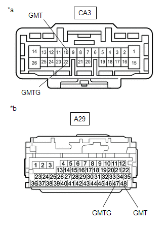
                  (d) Reconnect the A29 hybrid vehicle control ECU assembly connector. 
                  (e) Reconnect the CA3 No. 1 engine room relay block and junction block assembly connector. 


                           | NG | 
                           
                               
                            | 
                           
                               REPAIR OR REPLACE HARNESS OR CONNECTOR 
                            | 


                                 | 
OK
 | 


                                  | 
                               
                            
                         | 


                           | 
                               7.  
                            | 
                           
                               CHECK CONNECTOR CONNECTION CONDITION (GENERATOR TEMPERATURE SENSOR CONNECTOR) 
                            | 


                  Click here


                           | 
                               Result 
                            | 
                           
                               Proceed to 
                            | 


                           | 
                               OK 
                            | 
                           
                               A 
                            | 
                         
                        
                           | 
                               NG (The connector is not connected securely.) 
                            | 
                           
                               B 
                            | 
                         
                        
                           | 
                               NG (The terminals are not making secure contact or are deformed, or water or foreign matter exists in the connector.) 
                            | 
                           
                               C 
                            | 


                           | B | 
                           
                               
                            | 
                           
                               CONNECT SECURELY 
                            | 


                           | C | 
                           
                               
                            | 
                           
                               REPAIR OR REPLACE HARNESS OR CONNECTOR 
                            | 


                                 | 
A
 | 


                                  | 
                               
                            
                         | 


                           | 
                               8.  
                            | 
                           
                               CHECK HARNESS AND CONNECTOR (NO. 1 ENGINE ROOM RELAY BLOCK AND JUNCTION BLOCK ASSEMBLY - GENERATOR TEMPERATURE SENSOR) 
                            | 


                  (a) Disconnect the C50 generator temperature sensor connector. 
                  (b) Disconnect the CA3 No. 1 engine room relay block and junction block assembly connector. 


                           | 
                               (c) Measure the resistance according to the value(s) in the table below. 
                              Standard Resistance (Check for Open):  


                                       | 
                                           Tester Connection 
                                        | 
                                       
                                           Condition 
                                        | 
                                       
                                           Specified Condition 
                                        | 


                                       | 
                                           CA3-10 (GMT) - C50-5 (GMT) 
                                        | 
                                       
                                           Ignition switch off 
                                        | 
                                       
                                           Below 1 Ω 
                                        | 
                                     
                                    
                                       | 
                                           CA3-22 (GMTG) - C50-4 (GMTG) 
                                        | 
                                       
                                           Ignition switch off 
                                        | 
                                       
                                           Below 1 Ω 
                                        | 


                              Standard Resistance (Check for Short):  


                                       | 
                                           Tester Connection 
                                        | 
                                       
                                           Condition 
                                        | 
                                       
                                           Specified Condition 
                                        | 


                                       | 
                                           CA3-10 (GMT) - C50-5 (GMT) - Body ground and other terminals 
                                        | 
                                       
                                           Ignition switch off 
                                        | 
                                       
                                           10 kΩ or higher 
                                        | 
                                     
                                    
                                       | 
                                           CA3-22 (GMTG) - C50-4 (GMTG) - Body ground and other terminals 
                                        | 
                                       
                                           Ignition switch off 
                                        | 
                                       
                                           10 kΩ or higher 
                                        | 


                            | 


                                     | 


                                                | 
                                                    *a 
                                                 | 
                                                
                                                    Front view of wire harness connector 
                                                   (to Generator Temperature Sensor) 
                                                 | 
                                              
                                             
                                                | 
                                                    *b 
                                                 | 
                                                
                                                    Front view of wire harness connector 
                                                   (to No. 1 Engine Room Relay Block and Junction Block Assembly) 
                                                 | 


                                     | 
                                  
                               
                            | 


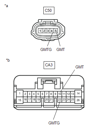
                  (d) Reconnect the CA3 No. 1 engine room relay block and junction block assembly connector. 
                  (e) Reconnect the C50 generator temperature sensor connector. 


                           | NG | 
                           
                               
                            | 
                           
                               REPAIR OR REPLACE HARNESS OR CONNECTOR 
                            | 


                           | 
                               9.  
                            | 
                           
                               INSPECT HYBRID VEHICLE TRANSAXLE ASSEMBLY (GENERATOR TEMPERATURE SENSOR) 
                            | 


                  (a) Disconnect the CA3 No. 1 engine room relay block and junction block assembly connector. 


                           | 
                               (b) Measure the resistance according to the value(s) in the table below. 
                              Standard Resistance:  


                                       | 
                                           Tester Connection 
                                        | 
                                       
                                           Condition 
                                        | 
                                       
                                           Specified Condition 
                                        | 


                                       | 
                                           CA3-10 (GMT) - CA3-22 (GMTG) 
                                        | 
                                       
                                           Ignition switch off 
                                        | 
                                       
                                           0.3338 to 1487 kΩ 
                                        | 


                            | 


                                     | 


                                                | 
                                                    *a 
                                                 | 
                                                
                                                    Front view of wire harness connector 
                                                   (to No. 1 Engine Room Relay Block and Junction Block Assembly) 
                                                 | 


                                     | 
                                  
                               
                            | 


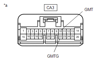
                  (c) Reconnect the CA3 No. 1 engine room relay block and junction block assembly connector. 


                           | OK | 
                           
                               
                            | 
                           
                               REPAIR OR REPLACE HARNESS OR CONNECTOR (HYBRID VEHICLE CONTROL ECU ASSEMBLY - NO. 1 ENGINE ROOM RELAY BLOCK AND JUNCTION BLOCK ASSEMBLY) 
                            | 


                                 | 
NG
 | 


                                  | 
                               
                            
                         | 


                           | 
                               10.  
                            | 
                           
                               INSPECT HYBRID VEHICLE TRANSAXLE ASSEMBLY (GENERATOR TEMPERATURE SENSOR) 
                            | 


                  Click here


                           | OK | 
                           
                               
                            | 
                           
                               REPAIR OR REPLACE HARNESS OR CONNECTOR (NO. 1 ENGINE ROOM RELAY BLOCK AND JUNCTION BLOCK ASSEMBLY - GENERATOR TEMPERATURE SENSOR) 
                            | 


                |