| 
                           Last Modified: 05-08-2025 | 
                        6.11:8.1.0  | 
                        
                           Doc ID: RM100000001OBDO | 
                      
                     
                        | 
                           Model Year Start: 2020 | 
                        
                           Model: RAV4 HV | 
                        
                           Prod Date Range: [06/2020 -                    
                                       ] | 
                      
                     
                        | 
                           Title: HYBRID / BATTERY CONTROL: HYBRID CONTROL SYSTEM (for LITHIUM-ION BATTERY): P0A1F94; Hybrid/EV Battery Energy Control Module Unexpected Operation; 2020 - 2025 MY RAV4 HV [06/2020 -        ] | 


                           | 
                               DTC 
                            | 
                           
                               P0A1F94 
                            | 
                           
                               Hybrid/EV Battery Energy Control Module Unexpected Operation 
                            | 


                  DTC SUMMARY
                  MALFUNCTION DESCRIPTION 
                  The hybrid vehicle control ECU assembly (main CPU) monitors the battery ECU assembly. 
                  The cause of this malfunction may be the following: 
                  
                     Battery ECU assembly internal malfunction
                     
                        - 
Battery ECU assembly malfunction


                  DESCRIPTION
                  The hybrid vehicle control ECU assembly (main CPU) monitors the battery ECU assembly and stores this DTC when it detects a malfunction. 


                           | 
                               DTC No. 
                            | 
                           
                               Detection Item 
                            | 
                           
                               DTC Detection Condition 
                            | 
                           
                               Trouble Area 
                            | 
                           
                               MIL 
                            | 
                           
                               Warning Indicate 
                            | 


                           | 
                               P0A1F94 
                            | 
                           
                               Hybrid/EV Battery Energy Control Module Unexpected Operation 
                            | 
                           
                               The battery ECU assembly value received by the hybrid vehicle control ECU assembly (main CPU) exceeds the threshold for a certain period of time. 
                              (1 trip detection logic) 
                            | 
                           
                               Battery ECU assembly 
                            | 
                           
                               Comes on 
                            | 
                           
                               Master Warning: 
                              Comes on 
                            | 


                  MONITOR DESCRIPTION
                  The battery ECU assembly monitors the hybrid vehicle control ECU assembly via CAN communication. If the battery ECU assembly detects a malfunction in the hybrid vehicle control ECU assembly, it will illuminate the MIL and store a DTC. 
                   
                  MONITOR STRATEGY


                           | 
                               Related DTCs 
                            | 
                           
                               P0A1F (INF P0A1F94): Battery Energy Control Module 
                            | 
                         
                        
                           | 
                               Required sensors/components 
                            | 
                           
                               Battery ECU assembly 
                            | 
                         
                        
                           | 
                               Frequency of operation 
                            | 
                           
                               Continuous 
                            | 
                         
                        
                           | 
                               Duration 
                            | 
                           
                               TMC's intellectual property 
                            | 
                         
                        
                           | 
                               MIL operation 
                            | 
                           
                               1 driving cycle 
                            | 
                         
                        
                           | 
                               Sequence of operation 
                            | 
                           
                               None 
                            | 


                  TYPICAL ENABLING CONDITIONS


                           | 
                               The monitor will run whenever the following DTCs are not stored 
                            | 
                           
                               TMC's intellectual property 
                            | 
                         
                        
                           | 
                               Other conditions belong to TMC's intellectual property 
                            | 
                           
                               - 
                            | 


                  TYPICAL MALFUNCTION THRESHOLDS


                           | 
                               TMC's intellectual property 
                            | 
                           
                               - 
                            | 


                  COMPONENT OPERATING RANGE


                           | 
                               Hybrid vehicle control ECU assembly 
                            | 
                           
                               P0A1F (INF P0A1F94) is not detected 
                            | 


                  CONFIRMATION DRIVING PATTERN
                  
                     HINT: 
                     
                        - 
After repair has been completed, clear the DTC and then check that the vehicle has returned to normal by performing the following All Readiness check procedure.
Click here


                        - 
When clearing the permanent DTCs, refer to the "CLEAR PERMANENT DTC" procedure.
Click here


                        - 
Connect the Techstream to the DLC3.
 
                        - 
Turn the ignition switch to ON and turn the Techstream on.
 
                        - 
Clear the DTCs (even if no DTCs are stored, perform the clear DTC procedure).
 
                        - 
Turn the ignition switch off and wait for 2 minutes or more.
 
                        - 
Turn the ignition switch to ON and turn the Techstream on.
 
                        - 
Turn the ignition switch to ON (READY) and wait for 10 seconds or more. [*1]
HINT: 
                           [*1] : Normal judgment procedure. 
                           The normal judgment procedure is used to complete DTC judgment and also used when clearing permanent DTCs. 
                         
                        - 
Enter the following menus: Powertrain / Hybrid Control / Utility / All Readiness.
 
                        - 
Check the DTC judgment result.
                              HINT: 
                              
                                 - 
If the judgment result shows NORMAL, the system is normal.
 
                                 - 
If the judgment result shows ABNORMAL, the system has a malfunction.
 
                                 - 
If the judgment result shows INCOMPLETE, perform the normal judgment procedure again.


                  PROCEDURE


                           | 
                               1.  
                            | 
                           
                               CHECK DTC OUTPUT (HYBRID CONTROL, HV BATTERY) 
                            | 


                  (a) Connect the Techstream to the DLC3. 
                  (b) Turn the ignition switch to ON. 
                  (c) Enter the following menus: Powertrain / Hybrid Control and HV Battery / Trouble Codes. 
                  (d) Check for DTCs. 
                  Powertrain > Hybrid Control > Trouble Codes
                  Powertrain > HV Battery > Trouble Codes


                           | 
                               Result 
                            | 
                           
                               Proceed to 
                            | 


                           | 
                               "P0A1F94" only is output, or DTCs except the ones in the table below are also output. 
                            | 
                           
                               A 
                            | 
                         
                        
                           | 
                               Simultaneous output of DTCs of hybrid control systems other than P0A1F94. 
                            | 
                           
                               B 
                            | 
                         
                        
                           | 
                               Any of the following DTCs are also output. 
                            | 
                           
                               C 
                            | 


                           | 
                               System 
                            | 
                           
                               Relevant DTC 
                            | 


                           | 
                               Hybrid battery system 
                            | 
                           
                               P1A001C 
                            | 
                           
                               Hybrid Battery Stack 2 Cell Voltage Detection Voltage Out of Range 
                            | 
                         
                        
                           | 
                               P301A1C 
                            | 
                           
                               Hybrid Battery Stack 1 Cell Voltage Detection Voltage Out of Range 
                            | 


                  (e) Turn the ignition switch off. 


                                 | 
C
 | 


                                  | 
                               
                            
                         | 


                  (a) Check the DTCs that were output when the vehicle was brought to the workshop. 


                           | 
                               Result 
                            | 
                           
                               Proceed to 
                            | 


                           | 
                               "P1A001C" is also output. 
                            | 
                           
                               A 
                            | 
                         
                        
                           | 
                               "P301A1C" is also output. 
                            | 
                           
                               B 
                            | 


                                 | 
A
 | 


                                  | 
                               
                            
                         | 


                           | 
                               3.  
                            | 
                           
                               CHECK CONNECTOR CONNECTION CONDITION (BATTERY ECU ASSEMBLY CONNECTOR) 
                            | 


                  CAUTION: 
                  Be sure to wear insulated gloves and protective goggles. 
                  (a) Check that the service plug grip is not installed. 
                  NOTICE: 
                  After removing the service plug grip, do not turn the ignition switch to ON (READY), unless instructed by the repair manual because this may cause a malfunction. 
                  (b) Remove the No. 1 HV battery hose. 
                  Click here


                           | 
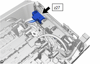
                               (c) Check the connections of the z27 battery ECU assembly connector. 
                              Click here


                              OK:  
                              The connector is connected securely and there are no contact problems. 
                            | 
                           
                              
                            | 


                  (d) Install the No. 1 HV battery hose. 


                           | 
                               Result 
                            | 
                           
                               Proceed to 
                            | 


                           | 
                               OK 
                            | 
                           
                               A 
                            | 
                         
                        
                           | 
                               Not connected securely 
                            | 
                           
                               The terminals are not damaged or corroded 
                            | 
                           
                               B 
                            | 
                         
                        
                           | 
                               Not connected securely 
                            | 
                           
                               The terminals are damaged or corroded 
                            | 
                           
                               C 
                            | 


                           | B | 
                           
                               
                            | 
                           
                               CONNECT SECURELY 
                            | 


                                 | 
A
 | 


                                  | 
                               
                            
                         | 


                           | 
                               4.  
                            | 
                           
                               CHECK FREEZE FRAME DATA 
                            | 


                  (a) Connect the Techstream to the DLC3. 
                  (b) Turn the ignition switch to ON. 
                  (c) Enter the following menus: Powertrain / HV battery / Trouble Codes. 
                  (d) Read the value of freeze frame data items "Hybrid/EV battery cell 36 voltage" through "Hybrid/EV battery cell 70 voltage" for DTC P1A001C and make a note if the value of any is 1.6 V or less. 
                  Powertrain > HV Battery > Trouble Codes
                  (e) Turn the ignition switch off. 


                                 | 
NEXT
 | 


                                  | 
                               
                            
                         | 


                           | 
                               5.  
                            | 
                           
                               CHECK NO. 2 HV SUPPLY STACK SUB-ASSEMBLY (HYBRID BATTERY CELL VOLTAGE) 
                            | 


                  Click here


                           | 
                               Result 
                            | 
                           
                               Proceed to 
                            | 


                           | 
                               The voltage between the terminals is 1.6 V or less. 
                            | 
                           
                               A 
                            | 
                         
                        
                           | 
                               Other than above 
                            | 
                           
                               B 
                            | 


                           | 
                               6.  
                            | 
                           
                               CHECK CONNECTOR CONNECTION CONDITION (BATTERY ECU ASSEMBLY CONNECTOR) 
                            | 


                  CAUTION: 
                  Be sure to wear insulated gloves and protective goggles. 
                  (a) Check that the service plug grip is not installed. 
                  NOTICE: 
                  After removing the service plug grip, do not turn the ignition switch to ON (READY), unless instructed by the repair manual because this may cause a malfunction. 
                  (b) Remove the No. 1 HV battery hose. 
                  Click here


                           | 
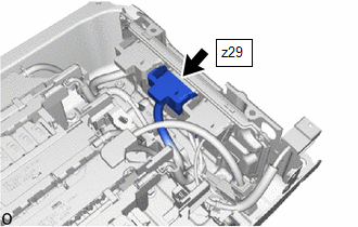
                               (c) Check the connections of the z29 battery ECU assembly connector. 
                              Click here


                              OK:  
                              The connector is connected securely and there are no contact problems. 
                              Result:  


                                       | 
                                           Result 
                                        | 
                                       
                                           Proceed to 
                                        | 


                                       | 
                                           OK 
                                        | 
                                       
                                           A 
                                        | 
                                     
                                    
                                       | 
                                           Not connected securely 
                                        | 
                                       
                                           The terminals are not damaged or corroded 
                                        | 
                                       
                                           B 
                                        | 
                                     
                                    
                                       | 
                                           Not connected securely 
                                        | 
                                       
                                           The terminals are damaged or corroded 
                                        | 
                                       
                                           C 
                                        | 


                            | 
                           
                              
                            | 


                  (d) Install the No. 1 HV battery hose. 


                           | B | 
                           
                               
                            | 
                           
                               CONNECT SECURELY 
                            | 


                                 | 
A
 | 


                                  | 
                               
                            
                         | 


                           | 
                               7.  
                            | 
                           
                               CHECK FREEZE FRAME DATA 
                            | 


                  (a) Connect the Techstream to the DLC3. 
                  (b) Turn the ignition switch to ON. 
                  (c) Enter the following menus: Powertrain / HV battery / Trouble Codes. 
                  (d) Read the value of freeze frame data items "Hybrid/EV battery cell 1 voltage" through "Hybrid/EV battery cell 35 voltage" for DTC P301A1C and make a note if the value of any is 1.6 V or less. 
                  Powertrain > HV Battery > Trouble Codes
                  (e) Turn the ignition switch off. 


                                 | 
NEXT
 | 


                                  | 
                               
                            
                         | 


                           | 
                               8.  
                            | 
                           
                               CHECK NO. 1 HV SUPPLY STACK SUB-ASSEMBLY (HYBRID BATTERY CELL VOLTAGE) 
                            | 


                  Click here


                           | 
                               Result 
                            | 
                           
                               Proceed to 
                            | 


                           | 
                               The voltage between the terminals is 1.6 V or less. 
                            | 
                           
                               A 
                            | 
                         
                        
                           | 
                               Other than above 
                            | 
                           
                               B 
                            | 


                |