| Last Modified: 11-18-2025 | 6.11:8.1.0 | Doc ID: RM100000001OR2K |
| Model Year Start: 2020 | Model: RAV4 HV | Prod Date Range: [06/2020 - ] |
| Title: HYBRID / BATTERY CONTROL: REAR MOTOR GENERATOR CONTROL SYSTEM (for LITHIUM-ION BATTERY): P0A7972; Drive Motor "B" Inverter Actuator Stuck Open; 2020 - 2025 MY RAV4 HV [06/2020 - ] | ||
|
DTC |
P0A7972 |
Drive Motor "B" Inverter Actuator Stuck Open |
DTC SUMMARY
MALFUNCTION DESCRIPTION
This DTC is stored when the rear motor control system is malfunctioning and current does not flow as commanded. The cause of this malfunction may be one of the following:
Internal inverter malfunction
- Inverter with converter assembly internal circuit malfunction
Inverter low-voltage circuit malfunction
- The connectors are not connected properly
DESCRIPTION
|
DTC No. |
Detection Item |
DTC Detection Condition |
Trouble Area |
MIL |
Warning Indicate |
|---|---|---|---|---|---|
|
P0A7972 |
Drive Motor "B" Inverter Actuator Stuck Open |
Malfunction is detected when offset component occurs in current flowing through motor with one phase open malfunction (1 trip detection logic) |
|
Comes on |
Master Warning: Comes on |
CONFIRMATION DRIVING PATTERN
HINT:
After repair has been completed, clear the DTC and then check that the vehicle has returned to normal by performing the following All Readiness check procedure.
Click here
![2020 - 2025 MY RAV4 HV [06/2020 - ]; HYBRID / BATTERY CONTROL: REAR MOTOR GENERATOR CONTROL SYSTEM (for LITHIUM-ION BATTERY): UTILITY](/t3Portal/stylegraphics/info.gif)
- Connect the Techstream to the DLC3.
- Turn the ignition switch to ON and turn the Techstream on.
- Clear the DTCs (even if no DTCs are stored, perform the clear DTC procedure).
- Turn the ignition switch off and wait for 2 minutes or more.
- Turn the ignition switch to ON and turn the Techstream on.
- Turn the ignition switch to ON (READY).
- Move the shift lever to D, and then accelerate until the vehicle speed is 20 km/h (12.5 mph) and the accelerator position is approximately 25%.
- Enter the following menus: Powertrain / Rear Motor Generator / Utility / All Readiness.
-
Check the DTC judgment result.
HINT:
- If the judgment result shows NORMAL, the system is normal.
- If the judgment result shows ABNORMAL, the system has a malfunction.
- If the judgment result shows INCOMPLETE, perform driving pattern again.
WIRING DIAGRAM
Refer to the wiring diagram for the Rear Motor High-voltage Circuit.
Click here
CAUTION / NOTICE / HINT
CAUTION:
-
Before the following operations are conducted, take precautions to prevent electric shock by turning the ignition switch off, wearing insulated gloves, and removing the service plug grip from HV battery.
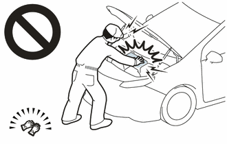
- Inspecting the high-voltage system
- Disconnecting the low voltage connector of the inverter with converter assembly
- Disconnecting the low voltage connector of the HV battery
-
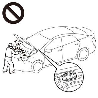
To prevent electric shock, make sure to remove the service plug grip to cut off the high voltage circuit before servicing the vehicle.
-
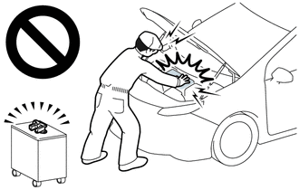
After removing the service plug grip from the HV battery, put it in your pocket to prevent other technicians from accidentally reconnecting it while you are working on the high-voltage system.
-
After removing the service plug grip, wait for at least 10 minutes before touching any of the high-voltage connectors or terminals. After waiting for 10 minutes, check the voltage at the terminals in the inspection point in the inverter with converter assembly. The voltage should be 0 V before beginning work.
Click here
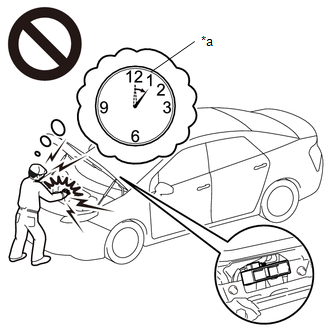
*a
Without waiting for 10 minutes
HINT:
Waiting for at least 10 minutes is required to discharge the high-voltage capacitor inside the inverter with converter assembly.
NOTICE:
After turning the ignition switch off, waiting time may be required before disconnecting the cable from the negative (-) auxiliary battery terminal. Therefore, make sure to read the disconnecting the cable from the negative (-) auxiliary battery terminal notices before proceeding with work.
Click here
PROCEDURE
PROCEDURE
|
1. |
GO TO MOTOR GENERATOR CONTROL SYSTEM |
(a) Go to Motor Generator Control System.
Click here
HINT:
For the P0A7972 inspection procedures, refer to the Motor Generator Control System section.
| NEXT |

|
END |
|
|
|