| Last Modified: 11-18-2025 | 6.11:8.1.0 | Doc ID: RM100000001OR2O |
| Model Year Start: 2020 | Model: RAV4 HV | Prod Date Range: [06/2020 - ] |
| Title: HYBRID / BATTERY CONTROL: REAR MOTOR GENERATOR CONTROL SYSTEM (for LITHIUM-ION BATTERY): P0BFE62,P1C681F; Drive Motor "B" Phase U-V-W Current Sensor Signal Compare Failure; 2020 - 2025 MY RAV4 HV [06/2020 - ] | ||
|
DTC |
P0BFE62 |
Drive Motor "B" Phase U-V-W Current Sensor Signal Compare Failure |
|
DTC |
P1C681F |
Drive Motor "B" Phase U-V-W Current Sensor Circuit Intermittent |
DTC SUMMARY
MALFUNCTION DESCRIPTION
These DTCs indicate that the current sensor value is abnormal. The cause of this malfunction may be one of the following:
Internal inverter malfunction
- Current sensor malfunction
- Inverter with converter assembly internal circuit malfunction
DESCRIPTION
|
DTC No. |
Detection Item |
DTC Detection Condition |
Trouble Area |
MIL |
Warning Indicate |
|---|---|---|---|---|---|
|
P0BFE62 |
Drive Motor "B" Phase U-V-W Current Sensor Signal Compare Failure |
Rear motor inverter current sensor characteristic malfunction: The value of the total output of the U, V and W phase current sensors exceeds the threshold.*1 (1 trip detection logic) |
|
Comes on |
Master Warning: Comes on |
|
P1C681F |
Drive Motor "B" Phase U-V-W Current Sensor Circuit Intermittent |
The value of the total output of the U, V and W phase current sensors exceeds the threshold detected when DTC P0C7917, P0D3319, P1C5D19, P1C5F19 or P1C5E19 is stored. (1 trip detection logic) |
|
Does not come on |
Master Warning: Does not come on |
HINT:
*1: Under normal conditions, the value of the total output of the U, V and W phase current sensors is approximately 0.
CONFIRMATION DRIVING PATTERN
HINT:
After repair has been completed, clear the DTC and then check that the vehicle has returned to normal by performing the following All Readiness check procedure.
Click here
![2020 - 2025 MY RAV4 HV [06/2020 - ]; HYBRID / BATTERY CONTROL: REAR MOTOR GENERATOR CONTROL SYSTEM (for LITHIUM-ION BATTERY): UTILITY](/t3Portal/stylegraphics/info.gif)
- Connect the Techstream to the DLC3.
- Turn the ignition switch to ON and turn the Techstream on.
- Clear the DTCs (even if no DTCs are stored, perform the clear DTC procedure).
- Turn the ignition switch off and wait for 2 minutes or more.
- Turn the ignition switch to ON and turn the Techstream on.
- Turn the ignition switch to ON (READY).
- Move the shift lever to D, and then accelerate until the vehicle speed is 20 km/h (12.5 mph) and the accelerator position is approximately 25%.
- Enter the following menus: Powertrain / Rear Motor Generator / Utility / All Readiness.
-
Check the DTC judgment result.
HINT:
- If the judgment result shows NORMAL, the system is normal.
- If the judgment result shows ABNORMAL, the system has a malfunction.
- If the judgment result shows INCOMPLETE, perform driving pattern again.
WIRING DIAGRAM
Refer to the wiring diagram for the Rear Motor High-voltage Circuit.
Click here
CAUTION / NOTICE / HINT
CAUTION:
-
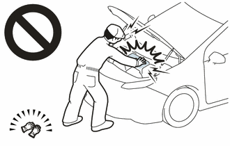
Before the following operations are conducted, take precautions to prevent electric shock by turning the ignition switch off, wearing insulated gloves, and removing the service plug grip from HV battery.
- Inspecting the high-voltage system
- Disconnecting the low voltage connector of the inverter with converter assembly
- Disconnecting the low voltage connector of the HV battery
-
To prevent electric shock, make sure to remove the service plug grip to cut off the high voltage circuit before servicing the vehicle.
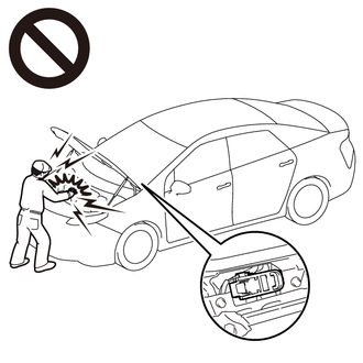
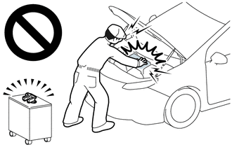
-
After removing the service plug grip from the HV battery, put it in your pocket to prevent other technicians from accidentally reconnecting it while you are working on the high-voltage system.
-
After removing the service plug grip, wait for at least 10 minutes before touching any of the high-voltage connectors or terminals. After waiting for 10 minutes, check the voltage at the terminals in the inspection point in the inverter with converter assembly. The voltage should be 0 V before beginning work.
Click here
HINT:
Waiting for at least 10 minutes is required to discharge the high-voltage capacitor inside the inverter with converter assembly.
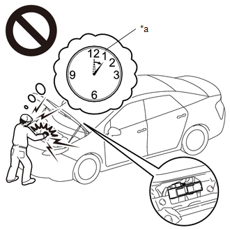
*a
Without waiting for 10 minutes
NOTICE:
After turning the ignition switch off, waiting time may be required before disconnecting the cable from the negative (-) auxiliary battery terminal. Therefore, make sure to read the disconnecting the cable from the negative (-) auxiliary battery terminal notices before proceeding with work.
Click here
PROCEDURE
PROCEDURE
|
1. |
GO TO MOTOR GENERATOR CONTROL SYSTEM |
(a) Go to Motor Generator Control System.
Click here
HINT:
For the P0BFE62 and P1C681F inspection procedures, refer to the Motor Generator Control System section.
| NEXT |

|
END |
|
|
|