| 
                           Last Modified: 05-08-2025 | 
                        6.11:8.1.0  | 
                        
                           Doc ID: RM100000001P4PU | 
                      
                     
                        | 
                           Model Year Start: 2020 | 
                        
                           Model: RAV4 HV | 
                        
                           Prod Date Range: [06/2020 - 08/2020] | 
                      
                     
                        | 
                           Title: A25A-FXS (FUEL): FUEL INJECTOR (for Port Injection): INSTALLATION; 2020 MY RAV4 HV [06/2020 - 08/2020] | 
                      
                   
                  INSTALLATION
                   
                  CAUTION / NOTICE / HINT
                  NOTICE: 
                  This procedure includes the installation of small-head bolts. Refer to Small-Head Bolts of Basic Repair Hint to identify the small-head bolts. 
                  Click here


                  PROCEDURE
                   
                  1. INSTALL PORT FUEL INJECTOR ASSEMBLY 
                  HINT: 
                  Perform "Inspection After Repair" after replacing a port fuel injector assembly. 
                  
                     
                        - 
w/ Canister Pump Module
Click here


                        - 
w/o Canister Pump Module
Click here


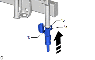
                  (a) Apply a light coat of spindle oil or gasoline to 4 new O-rings, and install 1 to each port fuel injector assembly. 
                  NOTICE: 
                  Check that there is no damage or foreign matter on the groove of the port fuel injector assembly when installing the O-ring to each port fuel injector assembly. 


                           | 
                               (b) Install the 4 port fuel injector assemblies to the fuel delivery pipe sub-assembly. 
                              
                                 NOTICE: 
                                 
                                    - 
Make sure that the port fuel injector assembly is located within the stopper as shown in the illustration.
 
                                    - 
Check that the port fuel injector assembly installation holes of the fuel delivery pipe sub-assembly are not damaged and are free of foreign matter.
 
                                    - 
Make sure that the O-ring is not damaged, twisted or moved out of place when installing the port fuel injector assembly.


                            | 
                           
                              
                            | 


                  2. INSTALL NO. 5 ENGINE WIRE 
                  (a) Attach the 2 clamps and install the No. 5 engine wire to the fuel delivery pipe sub-assembly. 
                  (b) Connect the 5 connectors to the 4 port fuel injector assemblies and fuel pressure sensor. 
                   
                  3. INSTALL INJECTOR VIBRATION INSULATOR 
                  (a) Install 4 new injector vibration insulators to the cylinder head sub-assembly. 
                   
                  4. INSTALL NO. 1 DELIVERY PIPE SPACER 


                           | 
                               (a) Install the 2 No. 1 delivery pipe spacers to the cylinder head sub-assembly. 
                              NOTICE: 
                              Install the No. 1 delivery pipe spacers in the correct direction. 
                            | 


                                     | 


                                                | 
                                                    *a 
                                                 | 
                                                
                                                    Fuel delivery pipe sub-assembly Side 
                                                 | 
                                              
                                             
                                                | 
                                                    *b 
                                                 | 
                                                
                                                    Cylinder Head Sub-assembly Side 
                                                 | 


                                     | 
                                  
                               
                            | 


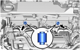
                  5. INSTALL FUEL DELIVERY PIPE SUB-ASSEMBLY 
                  (a) Place the fuel delivery pipe sub-assembly to the cylinder head sub-assembly. 
                  NOTICE: 
                  Be careful not to drop the port fuel injector assemblies when installing the fuel delivery pipe sub-assembly. 
                  (b) Install the fuel delivery pipe sub-assembly with the port fuel injector assemblies with the 2 bolts. 
                  Torque:  
                  28.5 N·m {291 kgf·cm, 21 ft·lbf} 
                  (c) Connect the connector to the No. 5 engine wire. 
                   
                  6. TEMPORARILY INSTALL NO. 1 FUEL PIPE SUB-ASSEMBLY 
                  Click here


                  7. INSTALL FUEL PUMP ASSEMBLY 
                  Click here


                  8. INSTALL NO. 1 FUEL PIPE SUB-ASSEMBLY 
                  Click here


                  9. CONNECT FUEL TUBE SUB-ASSEMBLY 
                  (a) Connect the fuel tube sub-assembly to the fuel delivery pipe sub-assembly. 
                  Click here


                  (b) Install the fuel pipe clamp to the fuel tube connector. 
                   
                  10. INSTALL NO. 2 WATER BY-PASS PIPE 
                  Click here


                  11. INSTALL EGR VALVE ASSEMBLY 
                  Click here


                  12. INSTALL THROTTLE BODY WITH MOTOR ASSEMBLY 
                  Click here


                  13. CONNECT CABLE TO NEGATIVE AUXILIARY BATTERY TERMINAL 
                  NOTICE: 
                  When disconnecting the cable, some systems need to be initialized after the cable is reconnected. 
                  Click here


                  14. INSTALL BATTERY HOLE COVER 
                  Click here


                  15. INSTALL REAR NO. 2 FLOOR BOARD 
                  Click here


                  16. INSTALL DECK BOARD ASSEMBLY 
                  Click here


                  17. INSPECT FOR FUEL LEAK 
                  Click here


                  18. PERFORM INITIALIZATION 
                  (a) Perform "Inspection After Repair" after replacing a port fuel injector assembly. 
                  
                     
                        - 
w/ Canister Pump Module:
Click here


                        - 
w/o Canister Pump Module:
Click here


                |