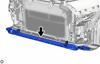
- Front television camera assembly (Including removal and installation)
- Radiator grille assembly (Including removal and installation)
| Last Modified: 01-30-2024 | 6.11:8.1.0 | Doc ID: RM100000001QIPM |
| Model Year Start: 2021 | Model: RAV4 | Prod Date Range: [08/2020 - 12/2021] |
| Title: EXTERIOR PANELS / TRIM: FRONT BUMPER (except Off Road Package): REMOVAL; 2021 MY RAV4 RAV4 HV [08/2020 - 12/2021] | ||
REMOVAL
CAUTION / NOTICE / HINT
The necessary procedures (adjustment, calibration, initialization or registration) that must be performed after parts are removed and installed, or replaced during front bumper assembly removal/installation are shown below.
Necessary Procedures After Parts Removed/Installed/Replaced (for HV Model)
|
Replaced Part or Performed Procedures |
Necessary Procedures |
Effect/Inoperative Function when Necessary Procedures are not Performed |
Link |
|---|---|---|---|
|
Front bumper assembly (Including removal and installation) |
Front television camera view adjustment |
Panoramic view monitor system (for HV Model) |
|
|
|
Front television camera view adjustment |
Panoramic view monitor system (for HV model) |
|
|
Front television camera assembly, radiator grille assembly or front bumper assembly |
Television camera view adjustment |
Panoramic view monitor system (for HV model) |
Necessary Procedures After Parts Removed/Installed/Replaced (for Gasoline Model)
|
Replaced Part or Performed Procedures |
Necessary Procedures |
Effect/Inoperative Function when Necessary Procedures are not Performed |
Link |
|---|---|---|---|
|
Front bumper assembly (Including removal and installation) |
Front television camera view adjustment |
Panoramic view monitor system (for Gasoline Model) |
|
|
Front television camera view adjustment |
Panoramic view monitor system (for Gasoline model) |
|
|
Front television camera assembly, radiator grille assembly or front bumper assembly |
Television camera view adjustment |
Panoramic view monitor system (for Gasoline model) |
HINT:
- When the front bumper is damaged or deformed due to an accident or contact with other objects, etc., or the bumper installation area on the body is repaired, it is necessary to perform millimeter wave radar sensor adjustment.
- When the front bumper is damaged or deformed due to an accident or contact with other objects, etc., or the bumper installation area on the body is repaired, it is necessary to perform ultrasonic sensor detection angle measurement.
PROCEDURE
1. REMOVE FRONT FENDER FRONT SPLASH SHIELD LH
HINT:
Use the same procedure described for the RH side.
(a) for Short Type:
(b) for Long Type:
2. REMOVE FRONT FENDER FRONT SPLASH SHIELD RH
HINT:
Use the same procedure as for the RH and LH sides.
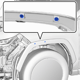
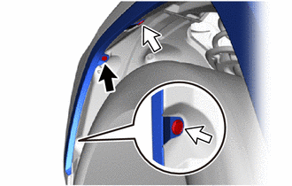
3. REMOVE FRONT FENDER MOULDING SUB-ASSEMBLY LH
(a) Remove the screw.

|
Screw |

|
Clip |
(b) Remove the 2 clips.
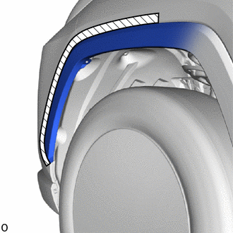
(c) Put protective tape around the front fender moulding sub-assembly LH.

|
Protective Tape |
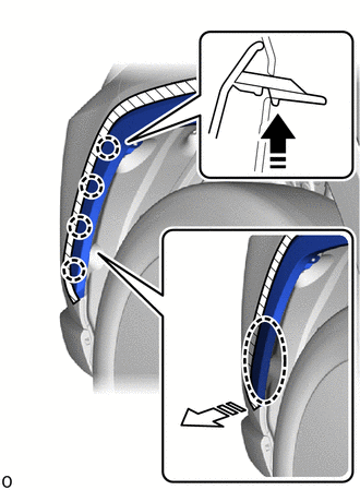
(d) Pull back the edge of the front fender liner LH and detach the claw by pushing the area indicated by the arrow in the illustration with a finger.

|
Place Hand Here |

|
Remove in this Direction(1) |

|
Remove in this Direction(2) |
NOTICE:
- Do not apply excessive force when pulling back the front fender liner LH.
- To avoid damaging the claws, do not forcibly pull the front fender moulding sub-assembly LH.
(e) Detach the clip and disconnect the front fender moulding sub-assembly LH as shown in the illustration.
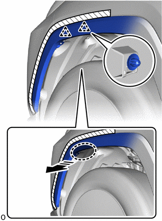

|
Place Hand Here |

|
Remove in this Direction |
4. REMOVE FRONT FENDER MOULDING SUB-ASSEMBLY RH
HINT:
Use the same procedure as for the LH side.
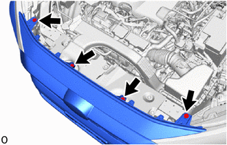
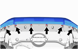
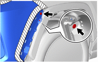
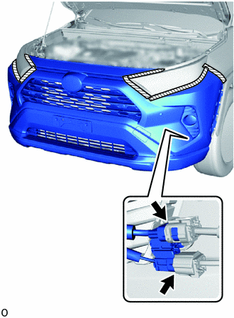
5. REMOVE FRONT BUMPER ASSEMBLY
|
(a) Remove the 4 bolts. |
|
|
(b) Remove the 6 screws. |
|
(c) Put protective tape around the front bumper assembly.
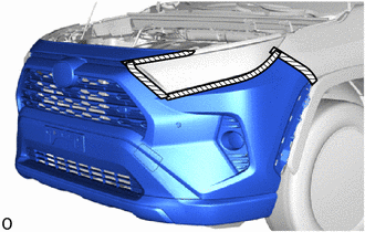

|
Protective Tape |
HINT:
Use the same procedure as for the RH and LH sides.
|
(d) Remove the 2 clips. HINT: Use the same procedure as for the RH and LH sides. |
|
(e) Place your hand at the positions shown in the illustration and pull in the removal direction to detach the claw.
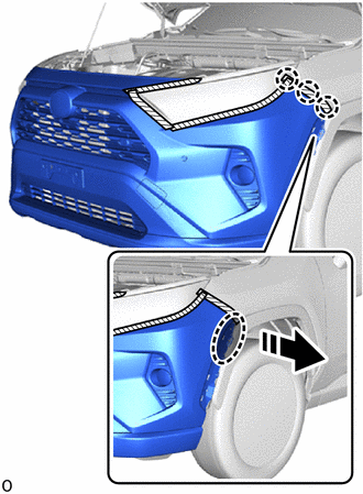

|
Place Hand Here |

|
Remove in this Direction |
HINT:
Use the same procedure as for the RH and LH sides.
|
(f) Pull back the edge of the front fender liner LH and disconnect the 2 connectors. |
|
(g) Detach the claw and remove the front bumper assembly.
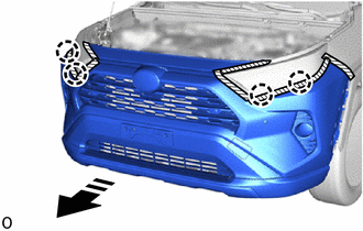

|
Remove in this Direction |
|
(h) Remove the 2 clips from the front fender moulding sub-assembly LH. NOTICE: If the front bumper assembly has been removed, replace the clip with a new one. HINT: Use the same procedure as for the RH and LH sides. |
|
6. REMOVE FRONT BUMPER SIDE RETAINER LH
HINT:
Perform the following procedure only when replacement of a front bumper side retainer LH is necessary.
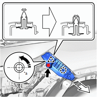
(a) Remove the bolt.
|
*a |
90° |

|
Rotation Direction |

|
Remove in this Direction |
(b) Using a screwdriver, turn the clip 90° and detach the clip and claw and remove the front bumper side retainer LH as shown in the illustration.
7. REMOVE FRONT BUMPER SIDE RETAINER RH
HINT:
- Perform the following procedure only when replacement of a front bumper side retainer RH is necessary.
- Use the same procedure as for the RH and LH sides.
8. REMOVE FRONT BUMPER NO. 2 ENERGY ABSORBER
HINT:
Perform the following procedure only when replacement of a front bumper No. 2 energy absorber is necessary.
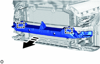
(a) Detach the guide and remove the front bumper No. 2 energy absorber.

|
Remove in this Direction |
9. REMOVE FRONT BUMPER REINFORCEMENT SUB-ASSEMBLY
HINT:
Perform the following procedure only when replacement of a front bumper reinforcement sub-assembly is necessary.
|
(a) Detach the wire harness clamp. |
|
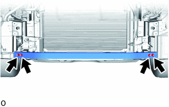
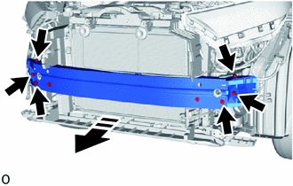
(b) Remove the 6 bolts and front bumper reinforcement sub-assembly as shown in the illustration.

|
Remove in this Direction |
10. REMOVE FRONT BUMPER NO. 2 REINFORCEMENT (for HV Model)
HINT:
Perform the following procedure only when replacement of a front bumper No. 2 reinforcement is necessary.
|
(a) Remove the 4 nuts and front bumper No. 2 reinforcement. |
|
11. REMOVE NO. 1 ENGINE UNDER COVER
HINT:
Perform the following procedure only when replacement of a front bumper extension sub-assembly LH and RH or front bumper lower absorber is necessary.
(a) for Gasoline Model:
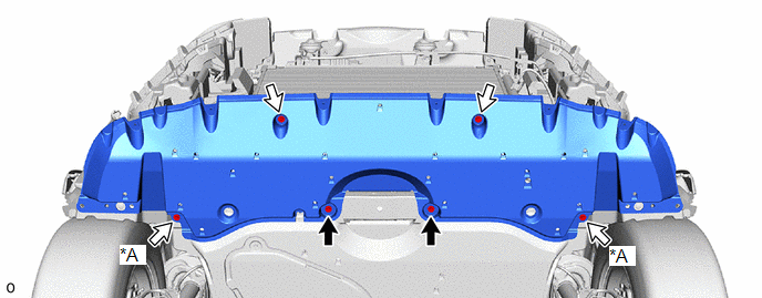
(1) Remove the 2 bolts and 2 screws.
|
*A |
for Short Front Fender Front Splash Shield |
- |
- |

|
Bolt |

|
Screw |
(2) for Short Front Fender Front Splash Shield:
Remove the 2 screws.
(b) for HV Model:
(1) Remove the 2 bolts.
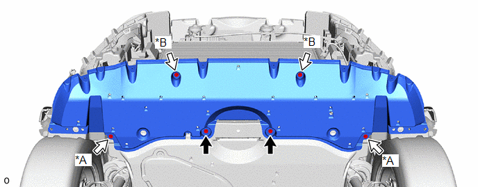
|
*A |
for Short Front Fender Front Splash Shield |
*B |
for Type B |

|
Bolt |

|
Screw |
(2) for Short Front Fender Front Splash Shield:
Remove the 2 screws.
(3) for Type B:
Remove the 2 screws.
(c) Detach the guide and remove the No. 1 engine under cover.
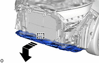

|
Remove in this Direction |
12. REMOVE FRONT BUMPER LOWER ABSORBER (for Gasoline Model)
HINT:
Perform the following procedure only when replacement of a front bumper lower absorber is necessary.
|
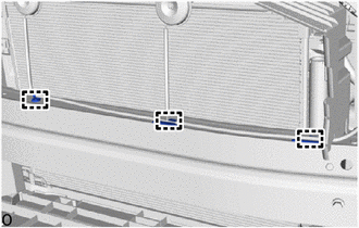
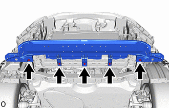
(a) Remove the 5 bolts. |
|
(b) Detach the guide and remove the front bumper lower absorber as shown in the illustration.
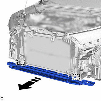

|
Remove in this Direction |
13. REMOVE FRONT BUMPER LOWER ABSORBER (for HV Model)
HINT:
Perform the following procedure only when replacement of a front bumper lower absorber is necessary.
|
(a) Remove the clip. |
|
(b) Detach the claw and remove the front bumper lower absorber.
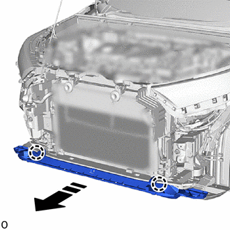

|
Remove in this Direction |
14. REMOVE FRONT BUMPER SEAL (for TMMC Made)
HINT:
- Perform the following procedure only when replacement of a front bumper seal is necessary.
- When removing the front bumper seal, if the double-sided tape is difficult to remove, heat the adhesive of the front bumper lower absorber and front bumper seal using a heat light.
Standard:
|
Item |
Temperature |
|---|---|
|
Front Bumper Lower Absorber |
20 to 30°C (68 to 86°F) |
|
Front Bumper Seal |
20 to 30°C (68 to 86°F) |
CAUTION:
- Do not touch the heat light and heated parts.
- Touching the heat light may result in burns.
- Touching heated parts for a long time may result in burns.
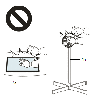
|
*a |
Heated Part |
|
*b |
Heat Light |
NOTICE:
Do not heat the front bumper lower absorber and front bumper seal excessively.
(a) Remove the 2 front bumper seals.
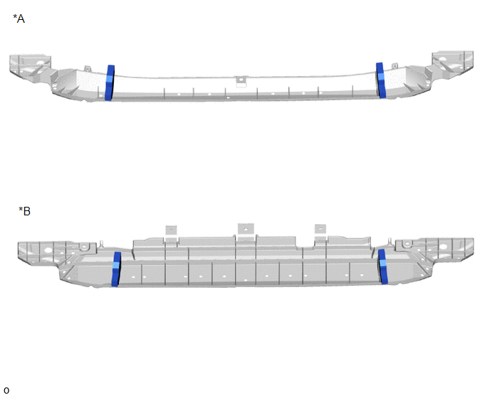
|
*A |
for HV Model |
*B |
for Gasoline Model |
15. REMOVE FRONT BUMPER EXTENSION SUB-ASSEMBLY LH
HINT:
Perform the following procedure only when replacement of a front bumper extension sub-assembly LH is necessary.
(a) Remove the 2 nuts, 2 bolts and front bumper extension sub-assembly LH.
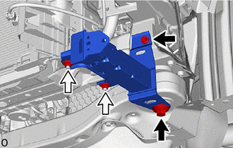

|
Bolt |

|
Nut |
16. REMOVE FRONT BUMPER EXTENSION SUB-ASSEMBLY RH
HINT:
- Perform the following procedure only when replacement of a front bumper extension sub-assembly RH is necessary.
- Use the same procedure as for the RH and LH sides.
|
|
|
![2019 - 2022 MY RAV4 HV [11/2018 - 10/2022]; PARK ASSIST / MONITORING: PANORAMIC VIEW MONITOR SYSTEM (for HV Model): CALIBRATION](/t3Portal/stylegraphics/info.gif)
