| Last Modified: 05-08-2025 | 6.11:8.1.0 | Doc ID: RM10000000201EY |
| Model Year Start: 2022 | Model: RAV4 HV | Prod Date Range: [12/2021 - 10/2022] |
| Title: HEATING / AIR CONDITIONING: COMPRESSOR (for A25A-FXS): REMOVAL; 2022 MY RAV4 HV [12/2021 - 10/2022] | ||
REMOVAL
CAUTION / NOTICE / HINT
The necessary procedures (adjustment, calibration, initialization, or registration) that must be performed after parts are removed, installed, or replaced during the compressor with motor assembly removal/installation are shown below.
Necessary Procedures After Parts Removed/Installed/Replaced
|
Replaced Part or Performed Procedure |
Necessary Procedure |
Effect/Inoperative Function when Necessary Procedure not Performed |
Link |
|---|---|---|---|
|
*: When performing learning using the Techstream.
Click here
|
|||
|
Auxiliary battery terminal is disconnected/reconnected |
Perform steering sensor zero point calibration |
Lane control system |
|
|
Parking support brake system (for HV model)* |
|||
|
Pre-collision system |
|||
|
Memorize steering angle neutral point |
Parking assist monitor system |
|
|
|
Panoramic view monitor system (for HV model) |
|
||
|
Reset back door close position |
Power back door system (for HV model) |
|
|
|
Back door lock initialization |
Power door lock control system |
|
|
CAUTION:
-
Orange wire harnesses and connectors indicate high-voltage circuits. To prevent electric shock, always follow the procedure described in the repair manual.
Click here
![2019 - 2025 MY RAV4 HV [02/2019 - ]; HYBRID / BATTERY CONTROL: HYBRID CONTROL SYSTEM (for AWD with NICKEL METAL HYDRIDE BATTERY): PRECAUTION](/t3Portal/stylegraphics/info.gif)
-
To prevent electric shock, wear insulated gloves when working on wire harnesses and components of the high voltage system.
NOTICE:
-
After the ignition switch is turned off, the radio and display receiver assembly records various types of memory and settings. As a result, after turning the ignition switch off, be sure to wait for the time specified in the following table before disconnecting the cable from the negative (-) auxiliary battery terminal.
Waiting Time before Disconnecting Cable from Negative (-) Auxiliary Battery Terminal
System Name
See Procedure
Vehicle enrolled in Toyota Audio Multimedia system or safety connect system
6 minutes
Vehicle not enrolled in Toyota Audio Multimedia system and safety connect system
1 minute
-
After turning the ignition switch off, waiting time may be required before disconnecting the cable from the negative (-) auxiliary battery terminal. Therefore, make sure to read the disconnecting the cable from the negative (-) auxiliary battery terminal notices before proceeding with work.
Click here
-
If metal dust is produced inside the compressor with motor assembly, it could cause a clog in the modulator. If any metal dust comes out, replace the cooler dryer inside the modulator also.
Click here
PROCEDURE
1. RECOVER REFRIGERANT FROM REFRIGERATION SYSTEM
Click here
2. REMOVE SERVICE PLUG GRIP
Click here
3. CHECK TERMINAL VOLTAGE
(a) Disconnect the engine room main wire.
Click here
(b) Remove the connector cover assembly.
Click here
(c) Check the terminal voltage.
Click here
(d) Install the connector cover assembly.
Click here
(e) Connect the engine room main wire.
Click here
4. REMOVE FRONT WHEEL RH
Click here
5. REMOVE FRONT FENDER MOULDING SUB-ASSEMBLY RH (for TMC Made)
HINT:
Use the same procedure described as for the LH side.
Click here
6. REMOVE FRONT FENDER FRONT OUTSIDE MOULDING RH (for TMMC Made)
HINT:
Use the same procedure described as for the front fender moulding sub-assembly RH (for TMC Made).
7. REMOVE FRONT FENDER FRONT SPLASH SHIELD LH
Click here
8. REMOVE FRONT FENDER FRONT SPLASH SHIELD RH
Click here
9. REMOVE NO. 1 ENGINE UNDER COVER
Click here
10. REMOVE FRONT FENDER MUDGUARD RH (w/ Mudguard)
(a) for Short Type:
HINT:
Use the same procedure described as for the LH side.
Click here
(b) for Long Type:
HINT:
Use the same procedure described as for the LH side.
Click here
11. REMOVE FRONT FENDER APRON SEAL RH (for TMC Made)
Click here
12. REMOVE FRONT FENDER APRON SEAL RH (for TMMC Made)
HINT:
Use the same procedure described as for the front fender apron seal RH (for TMC Made).
13. REMOVE FRONT FENDER LINER RH
Click here
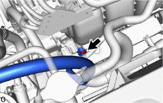
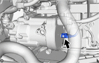
14. DISCONNECT SUCTION HOSE SUB-ASSEMBLY
|
(a) Remove the bolt and disconnect the suction hose sub-assembly. NOTICE: Do not apply excessive force to the suction hose sub-assembly. |
|
(b) Remove the O-ring from the suction hose sub-assembly.
NOTICE:
Seal the openings of the disconnected parts using vinyl tape to prevent moisture and foreign matter from entering them.
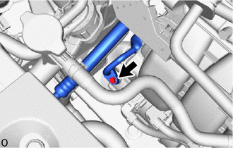
15. DISCONNECT NO. 1 COOLER REFRIGERANT DISCHARGE HOSE
|
(a) Remove the bolt and disconnect the No. 1 cooler refrigerant discharge hose. NOTICE: Do not apply excessive force to the No. 1 cooler refrigerant discharge hose. |
|
(b) Remove the O-ring from the No. 1 cooler refrigerant discharge hose.
NOTICE:
Seal the openings of the disconnected parts using vinyl tape to prevent moisture and foreign matter from entering them.
16. REMOVE COMPRESSOR WITH MOTOR ASSEMBLY
(a) Disconnect the connector (A).

|
Connector (A) |
|
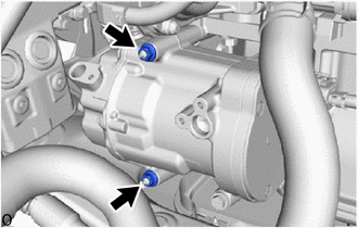
(b) Remove the 2 nuts. |
|
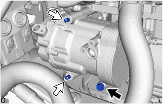
(c) Using an E8 "TORX" socket wrench, remove the 2 stud bolts and bolt.
NOTICE:
Do not drop or subject the parts to any impact.
|
|
Bolt |

|
Stud Bolt |
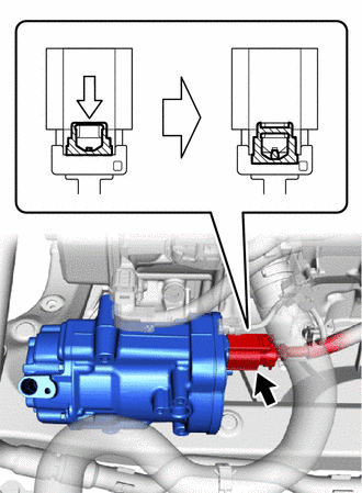
(d) Slide the green-colored lock of the connector (B) as shown in the illustration to release it and disconnect the connector.
|
|
Connector (B) |
|
|
Slide |

|
Green-colored Lock |
CAUTION:
Make sure to wear insulated gloves.
NOTICE:
Insulate the disconnected terminals and connector with insulating tape.
|
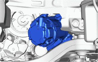
(e) Remove the compressor with motor assembly from the location shown in the illustration. NOTICE: Do not damage surrounding parts. |
|
|
|
|