| 
                           Last Modified: 05-08-2025 | 
                        6.11:8.1.0  | 
                        
                           Doc ID: RM10000000214QH | 
                      
                     
                        | 
                           Model Year Start: 2022 | 
                        
                           Model: RAV4 | 
                        
                           Prod Date Range: [12/2021 -                    
                                       ] | 
                      
                     
                        | 
                           Title: BRAKE CONTROL / DYNAMIC CONTROL SYSTEMS: ELECTRONICALLY CONTROLLED BRAKE SYSTEM (w/o Vacuum Brake Booster): C137BA2; Brake System Control Module "A" System Voltage System Voltage Low; 2022 - 2025 MY RAV4 RAV4 HV [12/2021 -        ] | 


                           | 
                               DTC 
                            | 
                           
                               C137BA2 
                            | 
                           
                               Brake System Control Module "A" System Voltage System Voltage Low 
                            | 


                  DESCRIPTION
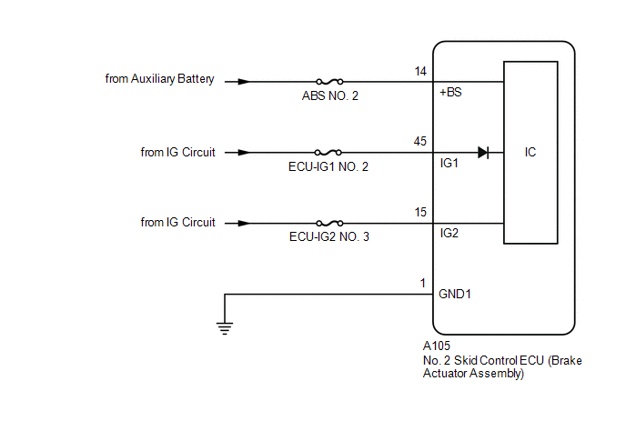
                  If a malfunction is detected in the power supply circuit, the No. 2 skid control ECU (brake actuator assembly) stores this DTC and the fail-safe function prohibits operation of ABS, brake assist, regenerative brake cooperative control, etc. 
                  This DTC is stored when the +BS, IG1 or IG2 terminal voltage meets one of the DTC detection conditions due to a malfunction in the power supply or charging circuit such as the auxiliary battery or DC/DC converter circuit, etc. 
                  This DTC is cleared when the voltage at terminal +BS, IG1 and IG2 returns to normal. 


                           | 
                               DTC No. 
                            | 
                           
                               Detection Item 
                            | 
                           
                               DTC Detection Condition 
                            | 
                           
                               Trouble Area 
                            | 
                           
                               MIL 
                            | 
                           
                               Note 
                            | 


                           | 
                               C137BA2 
                            | 
                           
                               Brake System Control Module "A" System Voltage System Voltage Low 
                            | 
                           
                               Any of the following is detected: 
                              
                                 
                                    - 
When the voltage at terminal +BS is less than 8.5 V, the master cylinder pressure sensor is invalid for 10 seconds or more.
 
                                    - 
When the voltage at terminal +BS is less than 8.5 V, the brake pedal stroke sensor assembly is invalid for 10 seconds or more.
 
                                    - 
When the +BS terminal voltage is below 9.5 V, the power source voltage for all speed sensors is continuously low for 60 seconds or more.
 
                                    - 
When the vehicle speed is 3 km/h (2 mph) or more, the voltage at terminal IG1 or terminal IG2 is excessively low for 10 seconds or more.
 
                                    - 
When the +BS terminal voltage is below 9.5 V and the solenoid relay is ON, the relay contact is OFF continuously for 1.22 seconds or more.
 
                                    - 
When the +BS terminal voltage is below 9.5 V, motor fail-safe relay overcurrent continues for 1.05 seconds or more.


                            | 


                                    - 
Wire harness and connector
 
                                    - 
No. 2 skid control ECU (brake actuator assembly)


                            | 
                           
                               Comes on 
                            | 


                                    - 
SAE Code: C137C
 
                                    - 
Output ECU: No. 2 skid control ECU (brake actuator assembly)


                            | 


                  C137BA2 DTC Detection Conditions


                           |   | 
                           
                               Vehicle Condition 
                            | 
                         
                        
                           | 
                               Pattern 1 
                            | 
                           
                               Pattern 2 
                            | 
                           
                               Pattern 3 
                            | 
                           
                               Pattern 4 
                            | 
                           
                               Pattern 5 
                            | 
                           
                               Pattern 6 
                            | 
                           
                               Pattern 7 
                            | 


                           | 
                               Diagnosis Condition 
                            | 
                           
                               When the voltage at terminal +BS is less than 8.5 V 
                            | 
                           
                               ○ 
                            | 
                           
                               ○ 
                            | 
                           
                               - 
                            | 
                           
                               - 
                            | 
                           
                               - 
                            | 
                           
                               - 
                            | 
                           
                               - 
                            | 
                         
                        
                           | 
                               When the +BS terminal voltage is below 9.5 V 
                            | 
                           
                               - 
                            | 
                           
                               - 
                            | 
                           
                               ○ 
                            | 
                           
                               - 
                            | 
                           
                               - 
                            | 
                           
                               - 
                            | 
                           
                               ○ 
                            | 
                         
                        
                           | 
                               When the vehicle speed is 3 km/h (2 mph) or more 
                            | 
                           
                               - 
                            | 
                           
                               - 
                            | 
                           
                               - 
                            | 
                           
                               ○ 
                            | 
                           
                               ○ 
                            | 
                           
                               - 
                            | 
                           
                               - 
                            | 
                         
                        
                           | 
                               When the +BS terminal voltage is below 9.5 V and the solenoid relay is ON 
                            | 
                           
                               - 
                            | 
                           
                               - 
                            | 
                           
                               - 
                            | 
                           
                               - 
                            | 
                           
                               - 
                            | 
                           
                               ○ 
                            | 
                           
                               - 
                            | 
                         
                        
                           | 
                               Malfunction Status 
                            | 
                           
                               The master cylinder pressure sensor is invalid 
                            | 
                           
                               ○ 
                            | 
                           
                               - 
                            | 
                           
                               - 
                            | 
                           
                               - 
                            | 
                           
                               - 
                            | 
                           
                               - 
                            | 
                           
                               - 
                            | 
                         
                        
                           | 
                               The brake pedal stroke sensor assembly is invalid 
                            | 
                           
                               - 
                            | 
                           
                               ○ 
                            | 
                           
                               - 
                            | 
                           
                               - 
                            | 
                           
                               - 
                            | 
                           
                               - 
                            | 
                           
                               - 
                            | 
                         
                        
                           | 
                               The power source voltage for all speed sensors is continuously low 
                            | 
                           
                               - 
                            | 
                           
                               - 
                            | 
                           
                               ○ 
                            | 
                           
                               - 
                            | 
                           
                               - 
                            | 
                           
                               - 
                            | 
                           
                               - 
                            | 
                         
                        
                           | 
                               The voltage at terminal IG1 is excessively low 
                            | 
                           
                               - 
                            | 
                           
                               - 
                            | 
                           
                               - 
                            | 
                           
                               ○ 
                            | 
                           
                               - 
                            | 
                           
                               - 
                            | 
                           
                               - 
                            | 
                         
                        
                           | 
                               The voltage at terminal IG2 is excessively low 
                            | 
                           
                               - 
                            | 
                           
                               - 
                            | 
                           
                               - 
                            | 
                           
                               - 
                            | 
                           
                               ○ 
                            | 
                           
                               - 
                            | 
                           
                               - 
                            | 
                         
                        
                           | 
                               The relay contact is OFF continuously 
                            | 
                           
                               - 
                            | 
                           
                               - 
                            | 
                           
                               - 
                            | 
                           
                               - 
                            | 
                           
                               - 
                            | 
                           
                               ○ 
                            | 
                           
                               - 
                            | 
                         
                        
                           | 
                               Motor fail-safe relay overcurrent continues 
                            | 
                           
                               - 
                            | 
                           
                               - 
                            | 
                           
                               - 
                            | 
                           
                               - 
                            | 
                           
                               - 
                            | 
                           
                               - 
                            | 
                           
                               ○ 
                            | 
                         
                        
                           | 
                               Detection Time 
                            | 
                           
                               10 seconds or more. 
                            | 
                           
                               10 seconds or more. 
                            | 
                           
                               60 seconds or more. 
                            | 
                           
                               10 seconds or more. 
                            | 
                           
                               10 seconds or more. 
                            | 
                           
                               1.22 seconds or more. 
                            | 
                           
                               1.05 seconds or more. 
                            | 
                         
                        
                           | 
                               Number of Trips 
                            | 
                           
                               1 trip 
                            | 
                           
                               1 trip 
                            | 
                           
                               1 trip 
                            | 
                           
                               1 trip 
                            | 
                           
                               1 trip 
                            | 
                           
                               1 trip 
                            | 
                           
                               1 trip 
                            | 


                  HINT: 
                  DTC will be output when conditions for either of the patterns in the table above are met. 
                   
                  MONITOR DESCRIPTION
                  
                     C137C (Case 1):
                     
                        - 
When the voltage of IG1 or IG2 is excessively low, the No. 2 skid control ECU (brake actuator assembly) detects that the power supply voltage is excessively low, the MIL is illuminated and a DTC is stored.


                     C137C (Case 2):
                     
                        - 
When the power supply voltage to all speed sensors is excessively low, the No. 2 skid control ECU (brake actuator assembly) judges that the power supply voltage is excessively low, the MIL is illuminated and a DTC is stored.


                     C137C (Case 3 and 4):
                     
                        - 
When the voltage at terminal +BS is less than 8.5 V and the data of the master cylinder pressure sensor, brake pedal stroke sensor assembly or wheel cylinder pressure sensor is invalid for a certain amount of time, the No. 2 skid control ECU (brake actuator assembly) judges that the power supply voltage is excessively low, the MIL is illuminated and a DTC is stored.


                     C137C (Case 5):
                     
                        - 
When the power supply voltage of the solenoid is excessively low for a certain amount of time, the No. 2 skid control ECU (brake actuator assembly) judges that the output of the solenoid relay is abnormal due to excessively low voltage, the MIL is illuminated and a DTC is stored.


                     C137C (Case 6):
                     
                        - 
The No. 2 skid control ECU (brake actuator assembly) monitors the current of the motor fail-safe relay. When overcurrent is detected in the motor circuit, the No. 2 skid control ECU (brake actuator assembly) judges that the motor output is abnormal due to excessively low voltage, the MIL is illuminated and a DTC is stored.


                  MONITOR STRATEGY


                           | 
                               Related DTCs 
                            | 
                           
                               C137C: Brake system voltage input out of range low 
                            | 
                         
                        
                           | 
                               Required Sensors/Components(Main) 
                            | 
                           
                               No. 2 skid control ECU (brake actuator assembly) 
                            | 
                         
                        
                           | 
                               Required Sensors/Components(Related) 
                            | 
                           
                               No. 2 skid control ECU (brake actuator assembly) 
                              Speed sensor 
                            | 
                         
                        
                           | 
                               Frequency of Operation 
                            | 
                           
                               Continuous 
                            | 
                         
                        
                           | 
                               Duration 
                            | 
                           
                               1 second: C137C (Case 5 and 6) 
                              10 seconds: C137C (Case 1, 3 and 4) 
                              60 seconds: C137C (Case 2) 
                            | 
                         
                        
                           | 
                               MIL Operation 
                            | 
                           
                               Immediately 
                            | 
                         
                        
                           | 
                               Sequence of Operation 
                            | 
                           
                               None 
                            | 


                  TYPICAL ENABLING CONDITIONS
                  C137C (Case 1)


                           | 
                               Monitor runs whenever the following DTCs are not stored 
                            | 
                           
                               C1241: Brake system voltage input out of range low 
                              C137C (Case 2, 3, 4, 5 and 6): Brake system voltage input out of range low 
                            | 
                         
                        
                           | 
                               All of the following conditions are met 
                            | 
                           
                               A, B, C, D and E 
                            | 
                         
                        
                           | 
                               A.  IG1 
                            | 
                           
                               On 
                            | 
                         
                        
                           | 
                               B. Vehicle speed 
                            | 
                           
                               Higher than 3 km/h (1.86 mph) 
                            | 
                         
                        
                           | 
                               C.  IG2 
                            | 
                           
                               On 
                            | 
                         
                        
                           | 
                               D. +BS voltage 
                            | 
                           
                               9.5 V or more 
                            | 
                         
                        
                           | 
                               E. Either of the following conditions is met 
                            | 
                           
                               a or b 
                            | 
                         
                        
                           | 
                               a. Both of the following conditions are met 
                            | 
                           
                               - 
                            | 
                         
                        
                           | 
                               Communication status with hybrid control system 
                            | 
                           
                               Valid 
                            | 
                         
                        
                           | 
                               Ready state 
                            | 
                           
                               On 
                            | 
                         
                        
                           | 
                               b. Communication status with hybrid control system 
                            | 
                           
                               Invalid 
                            | 


                  C137C (Case 2)


                           | 
                               Monitor runs whenever the following DTCs are not stored 
                            | 
                           
                               C1241: Brake system voltage input out of range low 
                            | 
                         
                        
                           | 
                               Both of the following conditions are met 
                            | 
                           
                               - 
                            | 
                         
                        
                           | 
                               IG1 
                            | 
                           
                               On 
                            | 
                         
                        
                           | 
                               +BS voltage 
                            | 
                           
                               Less than 9.5 V 
                            | 


                  C137C (Case 3)


                           | 
                               Monitor runs whenever the following DTCs are not stored 
                            | 
                           
                               C123E: Brake system voltage input open circuit 
                              C0540 (Case 1) :Pressure sensor verify communication 
                              C0540 (Case 2 to 4) Pressure sensor range check 
                              C056B: Pressure sensor intermittent/erratic 
                              C122E: Pressure sensor input out of range low 
                              C122F: Pressure sensor input out of range high 
                            | 
                         
                        
                           | 
                               All of the following conditions are met 
                            | 
                           
                               A, B and C 
                            | 
                         
                        
                           | 
                               A. +BS voltage 
                            | 
                           
                               Less than 8.5 V 
                            | 
                         
                        
                           | 
                               B. Master cylinder pressure sensor start state 
                            | 
                           
                               On 
                            | 
                         
                        
                           | 
                               C. Both of the following conditions are met 
                            | 
                           
                               a and b 
                            | 
                         
                        
                           | 
                               a. History of ready state on 
                            | 
                           
                               On 
                            | 
                         
                        
                           | 
                               b. Either of the following conditions is met 
                            | 
                           
                               - 
                            | 
                         
                        
                           | 
                               Ready state 
                            | 
                           
                               On 
                            | 
                         
                        
                           | 
                               Communication status with hybrid control system 
                            | 
                           
                               Invalid 
                            | 


                  C137C (Case 4)


                           | 
                               Monitor runs whenever the following DTCs are not stored 
                            | 
                           
                               C123E: Brake system voltage input open circuit 
                            | 
                         
                        
                           | 
                               Both of the following conditions are met 
                            | 
                           
                               A and B 
                            | 
                         
                        
                           | 
                               A. +BS voltage 
                            | 
                           
                               Less than 8.5 V 
                            | 
                         
                        
                           | 
                               B. Both of the following conditions are met 
                            | 
                           
                               a and b 
                            | 
                         
                        
                           | 
                               a. History of ready state on 
                            | 
                           
                               On 
                            | 
                         
                        
                           | 
                               b. Either of the following conditions is met 
                            | 
                           
                               - 
                            | 
                         
                        
                           | 
                               Ready state 
                            | 
                           
                               On 
                            | 
                         
                        
                           | 
                               Communication status with hybrid control system 
                            | 
                           
                               Invalid 
                            | 


                  C137C (Case 5)


                           | 
                               Monitor runs whenever the following DTCs are not stored 
                            | 
                           
                               C0597: (Case 1) ABS hold solenoid circuit stuck 
                              C0597: (Case 2 to 5) ABS hold solenoid performance 
                              C1241: Brake system voltage input out of range low 
                              C12A7: ABS hold solenoid (FL) circuit low 
                              C12A8: ABS hold solenoid (FL) circuit high 
                              C12B2: ABS release solenoid (FL) circuit low 
                              C12B3: ABS release solenoid (FL) circuit high 
                              C12BD: ABS hold solenoid (FR) circuit low 
                              C12BE: ABS hold solenoid (FR) circuit high 
                              C12C8: ABS release solenoid (FR) circuit low 
                              C12C9: ABS release solenoid (FR) circuit high 
                              C12D3: ABS hold solenoid (RL) circuit low 
                              C12D4: ABS hold solenoid (RL) circuit high 
                              C12DE: ABS release solenoid (RL) circuit low 
                              C12DF: ABS release solenoid (RL) circuit high 
                              C12E9: ABS hold solenoid (RR) circuit low 
                              C12EA: ABS hold solenoid (RR) circuit high 
                              C12F4: ABS release solenoid (RR) circuit low 
                              C12F5: ABS release solenoid (RR) circuit high 
                              C12F6: ABS hold solenoid other functional 
                              C12F7: ABS hold solenoid other functional 
                              C137C (Case 1 to 4 and 6): Brake system voltage input out of range low 
                              C137D: Brake system voltage input out of range high 
                              C13BF: SM solenoid other functional 
                              C13C2: SM1 solenoid circuit low 
                              C13C3: SM1 solenoid circuit high 
                              C13CB: SM2 solenoid circuit low 
                              C13CC: SM2 solenoid circuit high 
                              C143B: Brake system voltage solenoid relay stuck 
                              C143C: Brake system voltage open circuit 
                            | 
                         
                        
                           | 
                               Diagmask during the cranking 
                            | 
                           
                               Off 
                            | 


                  C137C (Case 6)


                           | 
                               Monitor runs whenever the following DTCs are not stored 
                            | 
                           
                               C052B: ABS pump motor performance 
                              C052D: ABS pump motor circuit high 
                              C052E: ABS pump motor open circuit 
                              C055B: ABS pump motor voltage circuit low 
                              C1241: Brake system voltage input out of range low 
                              C137C (Case 1 to 5): Brake system voltage input out of range low 
                            | 
                         
                        
                           | 
                               Initial check end state 
                            | 
                           
                               Valid 
                            | 


                  TYPICAL MALFUNCTION THRESHOLDS
                  C137C (Case 1)


                           | 
                               Either of the following conditions is met 
                            | 
                           
                               - 
                            | 
                         
                        
                           | 
                               IG1 voltage 
                            | 
                           
                               10 V or less 
                            | 
                         
                        
                           | 
                               IG2 voltage 
                            | 
                           
                               10 V or less 
                            | 


                  C137C (Case 2)


                           | 
                               All of the following conditions are met 
                            | 
                           
                               - 
                            | 
                         
                        
                           | 
                               FR wheel speed sensor power voltage 
                            | 
                           
                               Less than 4.1 V 
                            | 
                         
                        
                           | 
                               FL wheel speed sensor power voltage 
                            | 
                           
                               Less than 4.1 V 
                            | 
                         
                        
                           | 
                               RR wheel speed sensor power voltage 
                            | 
                           
                               Less than 4.1 V 
                            | 
                         
                        
                           | 
                               RL wheel speed sensor power voltage 
                            | 
                           
                               Less than 4.1 V 
                            | 


                  C137C (Case 3)


                           | 
                               Master cylinder pressure sensor data validity 
                            | 
                           
                               Invalid 
                            | 


                  C137C (Case 4)


                           | 
                               Stroke sensor data validity 
                            | 
                           
                               Invalid 
                            | 


                  C137C (Case 5)


                           | 
                               Both of the following conditions are met 
                            | 
                           
                               - 
                            | 
                         
                        
                           | 
                               Power supply for solenoid voltage 
                            | 
                           
                               Less than 6 V 
                            | 
                         
                        
                           | 
                               +BS voltage 
                            | 
                           
                               Less than 9.5 V 
                            | 


                  C137C (Case 6)


                           | 
                               All of the following conditions are met 
                            | 
                           
                               - 
                            | 
                         
                        
                           | 
                               History of blocking motor relay 
                            | 
                           
                               Off 
                            | 
                         
                        
                           | 
                               Command to motor fail-safe relay 
                            | 
                           
                               On 
                            | 
                         
                        
                           | 
                               Motor circuit current 
                            | 
                           
                               264 A or more 
                            | 
                         
                        
                           | 
                               +BS voltage 
                            | 
                           
                               Less than 9.5 V 
                            | 


                  COMPONENT OPERATING RANGE
                  C137C (Case 1)


                           | 
                               Both of the following conditions are met 
                            | 
                           
                               - 
                            | 
                         
                        
                           | 
                               IG1 voltage 
                            | 
                           
                               Higher than 10 V 
                            | 
                         
                        
                           | 
                               IG2 voltage 
                            | 
                           
                               Higher than 10 V 
                            | 


                  C137C (Case 2, 5 and 6)


                           | 
                               +BS voltage 
                            | 
                           
                               9.5 V or more 
                            | 


                  C137C (Case 3)


                           | 
                               All of the following conditions are met 
                            | 
                           
                               A, B and C 
                            | 
                         
                        
                           | 
                               A. +BS voltage 
                            | 
                           
                               8.5 V or more 
                            | 
                         
                        
                           | 
                               B. Either of the following conditions is met 
                            | 
                           
                               a or b 
                            | 
                         
                        
                           | 
                               a. Ready state 
                            | 
                           
                               Off 
                            | 
                         
                        
                           | 
                               b. Both of the following conditions are met 
                            | 
                           
                               - 
                            | 
                         
                        
                           | 
                               Ready state 
                            | 
                           
                               On 
                            | 
                         
                        
                           | 
                               IG1 voltage 
                            | 
                           
                               Higher than 10 V 
                            | 
                         
                        
                           | 
                               C. Master cylinder pressure sensor data validity 
                            | 
                           
                               Valid 
                            | 


                  C137C (Case 4)


                           | 
                               All of the following conditions are met 
                            | 
                           
                               A, B and C 
                            | 
                         
                        
                           | 
                               A. +BS voltage 
                            | 
                           
                               8.5 V or more 
                            | 
                         
                        
                           | 
                               B. Either of the following conditions is met 
                            | 
                           
                               a or b 
                            | 
                         
                        
                           | 
                               a. Ready state 
                            | 
                           
                               Off 
                            | 
                         
                        
                           | 
                               b. Both of the following conditions are met 
                            | 
                           
                               - 
                            | 
                         
                        
                           | 
                               Ready state 
                            | 
                           
                               On 
                            | 
                         
                        
                           | 
                               IG1 voltage 
                            | 
                           
                               Higher than 10 V 
                            | 
                         
                        
                           | 
                               C. Stroke sensor data validity 
                            | 
                           
                               Valid 
                            | 


                  CONFIRMATION DRIVING PATTERN
                  NOTICE: 
                  When performing the normal judgment procedure, make sure that the driver door is closed and is not opened at any time during the procedure. 
                  
                     HINT: 
                     
                        - 
After repair has been completed, clear the DTC and then check that the vehicle has returned to normal by performing the following All Readiness check procedure.
 
                        - 
When clearing the permanent DTCs, refer to the "CLEAR PERMANENT DTC" procedure.


                        - 
Connect the GTS to the DLC3.
 
                        - 
Turn the ignition switch to ON and turn the GTS on.
 
                        - 
Clear the DTCs (even if no DTCs are stored, perform the clear DTC procedure).
 
                        - 
Turn the ignition switch off.
 
                        - 
Turn the ignition switch to ON (READY) and turn the GTS on.
 
                        - 
Drive the vehicle at a speed of 3 km/h (2 mph) for 1 minute. [*]
HINT: 
                           [*]: Normal judgment procedure. 
                           The normal judgment procedure is used to complete DTC judgment and also used when clearing permanent DTCs. 
                         
                        - 
Enter the following menus: Chassis / Brake/EPB / Utility / All Readiness.
 
                        - 
Check the DTC judgment result.
                              HINT: 
                              
                                 - 
If the judgment result shows NORMAL, the system is normal.
 
                                 - 
If the judgment result shows ABNORMAL, the system has a malfunction.
 
                                 - 
If the judgment result shows INCOMPLETE, perform driving pattern again.


                  WIRING DIAGRAM
                   
                   
                  CAUTION / NOTICE / HINT
                  
                     NOTICE: 
                     
                        - 
Inspect the fuses for circuits related to this system before performing the following procedure.
 
                        - 
Before performing troubleshooting, make sure to confirm that the auxiliary battery voltage is normal.
Click here


                        - 
After replacing the No. 2 skid control ECU (brake actuator assembly), perform "Calibration" after performing "Reset Memory".
Click here


                  PROCEDURE


                           | 
                               1.  
                            | 
                           
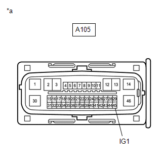
                               CHECK HARNESS AND CONNECTOR (IG1 TERMINAL) 
                            | 


                           | 
                               (a) Turn the ignition switch off. 
                            | 


                                     | 


                                                | 
                                                    *a 
                                                 | 
                                                
                                                    Front view of wire harness connector 
                                                   (to No. 2 Skid Control ECU (Brake Actuator Assembly)) 
                                                 | 


                                     | 
                                  
                               
                            | 


                  (b) Make sure that there is no looseness at the locking part and the connecting part of the connectors. 
                  OK:  
                  The connector is securely connected. 
                  (c) Disconnect the A105 No. 2 skid control ECU (brake actuator assembly) connector. 
                  (d) Check both the connector case and the terminals for deformation and corrosion. 
                  OK:  
                  No deformation or corrosion. 
                  (e) Turn the ignition switch to ON. 
                  (f) Measure the voltage according to the value(s) in the table below. 
                  Standard Voltage:  


                           | 
                               Tester Connection 
                            | 
                           
                               Condition 
                            | 
                           
                               Specified Condition 
                            | 


                           | 
                               A105-45 (IG1) - Body ground 
                            | 
                           
                               Ignition switch ON 
                            | 
                           
                               11 to 14 V 
                            | 


                           | NG | 
                           
                               
                            | 
                           
                               REPAIR OR REPLACE HARNESS OR CONNECTOR 
                            | 


                                 | 
OK
 | 


                                  | 
                               
                            
                         | 


                           | 
                               2.  
                            | 
                           
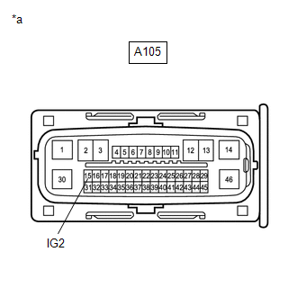
                               CHECK HARNESS AND CONNECTOR (IG2 TERMINAL) 
                            | 


                           | 
                               (a) Turn the ignition switch off. 
                            | 


                                     | 


                                                | 
                                                    *a 
                                                 | 
                                                
                                                    Front view of wire harness connector 
                                                   (to No. 2 Skid Control ECU (Brake Actuator Assembly)) 
                                                 | 


                                     | 
                                  
                               
                            | 


                  (b) Make sure that there is no looseness at the locking part and the connecting part of the connectors. 
                  OK:  
                  The connector is securely connected. 
                  (c) Disconnect the A105 No. 2 skid control ECU (brake actuator assembly) connector. 
                  (d) Check both the connector case and the terminals for deformation and corrosion. 
                  OK:  
                  No deformation or corrosion. 
                  (e) Turn the ignition switch to ON. 
                  (f) Measure the voltage according to the value(s) in the table below. 
                  Standard Voltage:  


                           | 
                               Tester Connection 
                            | 
                           
                               Condition 
                            | 
                           
                               Specified Condition 
                            | 


                           | 
                               A105-15 (IG2) - Body ground 
                            | 
                           
                               Ignition switch ON 
                            | 
                           
                               11 to 14 V 
                            | 


                           | NG | 
                           
                               
                            | 
                           
                               REPAIR OR REPLACE HARNESS OR CONNECTOR 
                            | 


                                 | 
OK
 | 


                                  | 
                               
                            
                         | 


                           | 
                               3.  
                            | 
                           
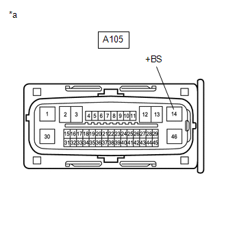
                               CHECK HARNESS AND CONNECTOR (+BS TERMINAL) 
                            | 


                           | 
                               (a) Turn the ignition switch off. 
                            | 


                                     | 


                                                | 
                                                    *a 
                                                 | 
                                                
                                                    Front view of wire harness connector 
                                                   (to No. 2 Skid Control ECU (Brake Actuator Assembly)) 
                                                 | 


                                     | 
                                  
                               
                            | 


                  (b) Make sure that there is no looseness at the locking part and the connecting part of the connectors. 
                  OK:  
                  The connector is securely connected. 
                  (c) Disconnect the A105 No. 2 skid control ECU (brake actuator assembly) connector. 
                  (d) Check both the connector case and the terminals for deformation and corrosion. 
                  OK:  
                  No deformation or corrosion. 
                  (e) Measure the voltage according to the value(s) in the table below. 
                  Standard Voltage:  


                           | 
                               Tester Connection 
                            | 
                           
                               Condition 
                            | 
                           
                               Specified Condition 
                            | 


                           | 
                               A105-14 (+BS) - Body ground 
                            | 
                           
                               Always 
                            | 
                           
                               11 to 14 V 
                            | 


                           | NG | 
                           
                               
                            | 
                           
                               REPAIR OR REPLACE HARNESS OR CONNECTOR 
                            | 


                                 | 
OK
 | 


                                  | 
                               
                            
                         | 


                           | 
                               4.  
                            | 
                           
                               CHECK HARNESS AND CONNECTOR (GND1 TERMINAL) 
                            | 


                  (a) Turn the ignition switch off. 
                  (b) Make sure that there is no looseness at the locking part and the connecting part of the connectors. 
                  OK:  
                  The connector is securely connected. 
                  (c) Disconnect the A105 No. 2 skid control ECU (brake actuator assembly) connector. 
                  (d) Check both the connector case and the terminals for deformation and corrosion. 
                  OK:  
                  No deformation or corrosion. 
                  (e) Measure the resistance according to the value(s) in the table below. 
                  Standard Resistance:  


                           | 
                               Tester Connection 
                            | 
                           
                               Condition 
                            | 
                           
                               Specified Condition 
                            | 


                           | 
                               A105-1 (GND1) - Body ground 
                            | 
                           
                               1 minute or more after disconnecting the cable from the negative (-) auxiliary battery terminal 
                            | 
                           
                               Below 1 Ω 
                            | 


                           | NG | 
                           
                               
                            | 
                           
                               REPAIR OR REPLACE HARNESS OR CONNECTOR 
                            | 


                                 | 
OK
 | 


                                  | 
                               
                            
                         | 


                  (a) Reconnect the A105 No. 2 skid control ECU (brake actuator assembly) connector. 
                  (b) Clear the DTCs. 
                  Chassis > Brake/EPB > Clear DTCs
                  (c) Turn the ignition switch off. 


                                 | 
NEXT
 | 


                                  | 
                               
                            
                         | 


                  (a) Based on the Freeze Frame Data and interview with the customer, attempt to reproduce the conditions when the malfunction occurred. 
                  (b) Check if the same DTC is output. 
                  Chassis > Brake/EPB > Trouble Codes


                           | 
                               Result 
                            | 
                           
                               Proceed to 
                            | 


                           | 
                               DTC C137BA2 is not output. 
                            | 
                           
                               A 
                            | 
                         
                        
                           | 
                               DTC C137BA2 is output. 
                            | 
                           
                               B 
                            | 


                |