| 
                           Last Modified: 05-08-2025 | 
                        6.11:8.1.0  | 
                        
                           Doc ID: RM10000000214R5 | 
                      
                     
                        | 
                           Model Year Start: 2022 | 
                        
                           Model: RAV4 | 
                        
                           Prod Date Range: [12/2021 -                    
                                       ] | 
                      
                     
                        | 
                           Title: BRAKE CONTROL / DYNAMIC CONTROL SYSTEMS: ELECTRONICALLY CONTROLLED BRAKE SYSTEM (w/o Vacuum Brake Booster): C14FE14; Steering Angle Sensor Supply Voltage Circuit Short to Ground or Open; 2022 - 2025 MY RAV4 RAV4 HV [12/2021 -        ] | 


                           | 
                               DTC 
                            | 
                           
                               C14FE14 
                            | 
                           
                               Steering Angle Sensor Supply Voltage Circuit Short to Ground or Open 
                            | 


                  DESCRIPTION
                  This DTC is stored when the No. 2 skid control ECU (brake actuator assembly) receives a power supply malfunction signal from the steering sensor. 


                           | 
                               DTC No. 
                            | 
                           
                               Detection Item 
                            | 
                           
                               DTC Detection Condition 
                            | 
                           
                               Trouble Area 
                            | 
                           
                               MIL 
                            | 
                           
                               Note 
                            | 


                           | 
                               C14FE14 
                            | 
                           
                               Steering Angle Sensor Supply Voltage Circuit Short to Ground or Open 
                            | 
                           
                               When the +BS terminal voltage is from 9.5 to 17.4 V, a steering sensor power supply malfunction signal is received from the steering sensor. 
                            | 


                                    - 
Steering sensor
 
                                    - 
Wire harness and connector


                            | 
                           
                               Does not come on 
                            | 
                           
                               Output ECU: No. 2 skid control ECU (brake actuator assembly) 
                            | 


                  WIRING DIAGRAM
                  Refer to DTC C05262A. 
                  Click here


                  CAUTION / NOTICE / HINT
                  NOTICE: 
                  Inspect the fuses for circuits related to this system before performing the following procedure. 
                   
                  PROCEDURE
                   
                  
                  (a) Clear the DTCs. 
                  Chassis > Brake/EPB > Clear DTCs
                  (b) Turn the ignition switch off. 


                                 | 
NEXT
 | 


                                  | 
                               
                            
                         | 


                  (a) Based on the Freeze Frame Data and interview with the customer, attempt to reproduce the conditions when the malfunction occurred. 
                  (b) Check if the same DTC is output. 
                  Chassis > Brake/EPB > Trouble Codes


                           | 
                               Result 
                            | 
                           
                               Proceed to 
                            | 


                           | 
                               DTC C14FE14 is not output. 
                            | 
                           
                               A 
                            | 
                         
                        
                           | 
                               DTC C14FE14 is output. 
                            | 
                           
                               B 
                            | 


                                 | 
B
 | 


                                  | 
                               
                            
                         | 


                           | 
                               3.  
                            | 
                           
                               CHECK HARNESS AND CONNECTOR (IG1 TERMINAL) 
                            | 


                           | 
                               (a) Make sure that there is no looseness at the locking part and the connecting part of the connectors. 
                              OK:  
                              The connector is securely connected. 
                            | 


                                     | 


                                                | 
                                                    *a 
                                                 | 
                                                
                                                    Front view of wire harness connector 
                                                   (to Steering Sensor) 
                                                 | 


                                     | 
                                  
                               
                            | 


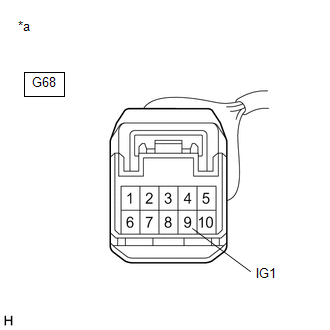
                  (b) Disconnect the G68 steering sensor connector. 
                  (c) Check both the connector case and the terminals for deformation and corrosion. 
                  OK:  
                  No deformation or corrosion. 
                  (d) Turn the ignition switch to ON. 
                  (e) Measure the voltage according to the value(s) in the table below. 
                  Standard Voltage:  


                           | 
                               Tester Connection 
                            | 
                           
                               Condition 
                            | 
                           
                               Specified Condition 
                            | 


                           | 
                               G68-9 (IG1) - Body ground 
                            | 
                           
                               Ignition switch ON 
                            | 
                           
                               11 to 14 V 
                            | 


                           | NG | 
                           
                               
                            | 
                           
                               REPAIR OR REPLACE HARNESS OR CONNECTOR 
                            | 


                                 | 
OK
 | 


                                  | 
                               
                            
                         | 


                           | 
                               4.  
                            | 
                           
                               CHECK HARNESS AND CONNECTOR (BAT TERMINAL) 
                            | 


                           | 
                               (a) Turn the ignition switch off. 
                            | 


                                     | 


                                                | 
                                                    *a 
                                                 | 
                                                
                                                    Front view of wire harness connector 
                                                   (to Steering Sensor) 
                                                 | 


                                     | 
                                  
                               
                            | 


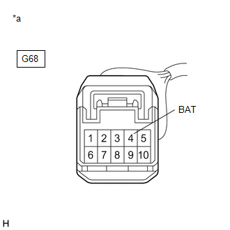
                  (b) Measure the voltage according to the value(s) in the table below. 
                  Standard Voltage:  


                           | 
                               Tester Connection 
                            | 
                           
                               Condition 
                            | 
                           
                               Specified Condition 
                            | 


                           | 
                               G68-4 (BAT) - Body ground 
                            | 
                           
                               Always 
                            | 
                           
                               11 to 14 V 
                            | 


                           | NG | 
                           
                               
                            | 
                           
                               REPAIR OR REPLACE HARNESS OR CONNECTOR 
                            | 


                                 | 
OK
 | 


                                  | 
                               
                            
                         | 


                           | 
                               5.  
                            | 
                           
                               CHECK HARNESS AND CONNECTOR (ESS TERMINAL) 
                            | 


                  (a) Measure the resistance according to the value(s) in the table below. 
                  Standard Resistance:  


                           | 
                               Tester Connection 
                            | 
                           
                               Condition 
                            | 
                           
                               Specified Condition 
                            | 


                           | 
                               G68-6 (ESS) - Body ground 
                            | 
                           
                               1 minute or more after disconnecting the cable from the negative (-) auxiliary battery terminal 
                            | 
                           
                               Below 1 Ω 
                            | 


                           | NG | 
                           
                               
                            | 
                           
                               REPAIR OR REPLACE HARNESS OR CONNECTOR 
                            | 


                |