
- Ignition switch ON
- The headlights are on
- The blower motor switch is in the HI position
- The rear window defogger is turned on
- Stop light switch assembly off (Brake pedal released)
| Last Modified: 05-08-2025 | 6.11:8.1.0 | Doc ID: RM10000000214R9 |
| Model Year Start: 2022 | Model: RAV4 | Prod Date Range: [12/2021 - ] |
| Title: BRAKE CONTROL / DYNAMIC CONTROL SYSTEMS: ELECTRONICALLY CONTROLLED BRAKE SYSTEM (w/o Vacuum Brake Booster): P057113; Brake Switch "A" Circuit Open; 2022 - 2025 MY RAV4 RAV4 HV [12/2021 - ] | ||
|
DTC |
P057113 |
Brake Switch "A" Circuit Open |
DESCRIPTION
The No. 2 skid control ECU (brake actuator assembly) detects the brake operating conditions through a signal transmitted by the stop light switch assembly.
The No. 2 skid control ECU (brake actuator assembly) incorporates a circuit to detect an open circuit.
This DTC is output when an open circuit is detected in the stop light signal input line.
|
DTC No. |
Detection Item |
DTC Detection Condition |
Trouble Area |
MIL |
Note |
|---|---|---|---|---|---|
|
P057113 |
Brake Switch "A" Circuit Open |
When the voltage at terminal +BS is 9.5 V or more and the stop light drive output (STPO) is off, an open in the STP circuit is detected for 10 seconds or more. |
|
Does not come on |
Output ECU: No. 2 skid control ECU (brake actuator assembly) |
WIRING DIAGRAM
Refer to DTC C13807E.
Click here
![2022 - 2025 MY RAV4 RAV4 HV [12/2021 - ]; BRAKE CONTROL / DYNAMIC CONTROL SYSTEMS: ELECTRONICALLY CONTROLLED BRAKE SYSTEM (w/o Vacuum Brake Booster): C13807E; Stop Lamp Relay Actuator Stuck On](/t3Portal/stylegraphics/info.gif)
CAUTION / NOTICE / HINT
NOTICE:
- Inspect the fuses for circuits related to this system before performing the following procedure.
-
After replacing the No. 2 skid control ECU (brake actuator assembly), perform "Calibration" after performing "Reset Memory".
Click here
PROCEDURE
|
1. |
CHECK STOP LIGHT OPERATION |
(a) Check that the stop lights come on when the brake pedal is depressed.
|
Result |
Proceed to |
|---|---|
|
All stop lights illuminate when the brake pedal is depressed and turn off when the brake pedal is released. |
A |
|
All stop lights do not illuminate when the brake pedal is depressed. |
B |
|
One or more stop lights illuminate when the brake pedal is depressed but remain on when the brake pedal is released. |
C |
| B |

|
| C |
|
|
|
2. |
READ VALUE USING GTS (STOP LIGHT SWITCH ASSEMBLY) |
(a) Check the value of Stop Light SW when the brake pedal is depressed.
Chassis > Brake/EPB > Data List
|
Tester Display |
Measurement Item |
Range |
Normal Condition |
Diagnostic Note |
|---|---|---|---|---|
|
Stop Light SW |
Stop light switch assembly status (STP or STP2 terminal input) |
OFF / ON |
OFF: Brake pedal released ON: Brake pedal depressed |
HINT:
|
Chassis > Brake/EPB > Data List
|
Tester Display |
|---|
|
Stop Light SW |
|
Result |
Proceed to |
|---|---|
|
The value of Stop Light SW is ON. |
A |
|
Other than above. |
B |
| B |
|
|
|
3. |
STOP LIGHT SWITCH ASSEMBLY OUTPUT CIRCUIT INSPECTION |
|
(a) Turn the ignition switch off. |
|
(b) Make sure that there is no looseness at the locking part and the connecting part of the connector.
OK:
The connector is securely connected.
(c) Turn the ignition switch to ON.
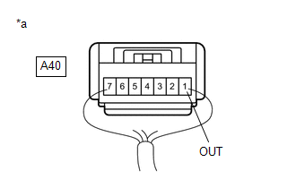
(d) Measure the voltage according to the value(s) in the table below.
Standard Voltage:
|
Tester Connection |
Condition |
Specified Condition |
|---|---|---|
|
A40-1 (OUT) - Body ground |
|
Below 1.5 V |
| NG |
|
|
|
4. |
CLEAR DTC |
(a) Clear the DTCs.
Chassis > Brake/EPB > Clear DTCs
(b) Turn the ignition switch off.
|
|
5. |
RECONFIRM DTC |
(a) Based on the Freeze Frame Data and interview with the customer, attempt to reproduce the conditions when the malfunction occurred.
(b) Check if the same DTC is output.
Chassis > Brake/EPB > Trouble Codes
|
Result |
Proceed to |
|---|---|
|
DTC P057113 is not output. |
A |
|
DTC P057113 is output. |
B |
| A |
|
| B |
|
REPLACE BRAKE ACTUATOR ASSEMBLY
|
|
6. |
CHECK STOP LIGHT SWITCH ASSEMBLY |
|
(a) Turn the ignition switch off. |
|
(b) Make sure that there is no looseness at the locking part and the connecting part of the connector.
OK:
The connector is securely connected.
(c) Disconnect the A40 stop light switch assembly connector.
(d) Check both the connector case and the terminals for deformation and corrosion.
OK:
No deformation or corrosion.
(e) Measure the voltage according to the value(s) in the table below.
Standard Voltage:
|
Tester Connection |
Condition |
Specified Condition |
|---|---|---|
|
A40-1 (OUT) - Body ground |
Stop light switch assembly off (Brake pedal released) |
Below 1.5 V |
| OK |
|
|
|
7. |
CHECK BRAKE ACTUATOR ASSEMBLY |
|
(a) Make sure that there is no looseness at the locking part and the connecting part of the connector. OK: The connector is securely connected. |
|
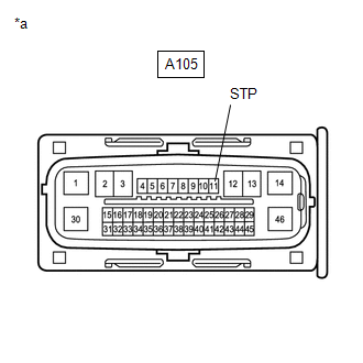
(b) Disconnect the A105 No. 2 skid control ECU (brake actuator assembly) connector.
(c) Check both the connector case and the terminals for deformation and corrosion.
OK:
No deformation or corrosion.
(d) Measure the voltage according to the value(s) in the table below.
Standard Voltage:
|
Tester Connection |
Condition |
Specified Condition |
|---|---|---|
|
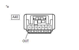
A40-1 (OUT) - Body ground |
Stop light switch assembly off (Brake pedal released) |
Below 1.5 V |
| OK |
|
REPLACE BRAKE ACTUATOR ASSEMBLY
|
|
|
8. |
CHECK FOR SHORT TO +B IN STP CIRCUIT |
(a) Check that there is no short to +B in the STP circuit (wire harnesses, connectors, ECUs and stop lights).
OK:
No short to +B.
| OK |
|
| NG |
|
REPAIR OR REPLACE MALFUNCTIONING PART |
|
9. |
CHECK HARNESS AND CONNECTOR (STP TERMINAL) |
|
(a) Turn the ignition switch off. |
|
(b) Make sure that there is no looseness at the locking part and the connecting part of the connector.
OK:
The connector is securely connected.
(c) Disconnect the A105 No. 2 skid control ECU (brake actuator assembly) connector.
(d) Check both the connector case and the terminals for deformation and corrosion.
OK:
No deformation or corrosion.
(e) Measure the voltage according to the value(s) in the table below.
Standard Voltage:
|
Tester Connection |
Condition |
Specified Condition |
|---|---|---|
|
A105-11 (STP) - Body ground |
Stop light switch assembly on (Brake pedal depressed) |
11 to 14 V |
| OK |
|
REPLACE BRAKE ACTUATOR ASSEMBLY
|
| NG |
|
REPAIR OR REPLACE HARNESS OR CONNECTOR |
|
10. |
CHECK HARNESS AND CONNECTOR (STOP LIGHT SWITCH ASSEMBLY - STOP LIGHT) |
(a) Check that there is no open in the wire harnesses and connectors from terminal OUT of the stop light switch assembly to the stop lights.
OK:
No open.
| OK |
|
REPLACE BRAKE ACTUATOR ASSEMBLY
|
| NG |
|
REPAIR OR REPLACE HARNESS OR CONNECTOR |
|
|
|