| Last Modified: 05-08-2025 | 6.11:8.1.0 | Doc ID: RM1000000021JWA |
| Model Year Start: 2022 | Model: RAV4 HV | Prod Date Range: [12/2021 - ] |
| Title: A25A-FXS (ENGINE MECHANICAL): ENGINE ASSEMBLY: INSTALLATION; 2022 - 2025 MY RAV4 HV [12/2021 - ] | ||
INSTALLATION
CAUTION / NOTICE / HINT
CAUTION:
- The engine assembly with transaxle is very heavy. Be sure to follow the procedure described in the repair manual, or the engine lifter may suddenly drop or the engine assembly with transaxle may fall off the engine lifter.
- To prevent burns, do not touch the engine, exhaust manifold or other high temperature components while the engine is hot.
NOTICE:
This procedure includes the removal of small-head bolts. Refer to Small-Head Bolts of Basic Repair Hint to identify the small-head bolts.
Click here
![2019 - 2025 MY RAV4 RAV4 HV [11/2018 - ]; INTRODUCTION: REPAIR INSTRUCTION: PRECAUTION](/t3Portal/stylegraphics/info.gif)
PROCEDURE
1. INSTALL ENGINE MOUNTING INSULATOR SUB-ASSEMBLY LH
HINT:
Perform this procedure only when replacement of the engine mounting insulator sub-assembly LH is necessary.
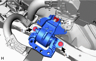
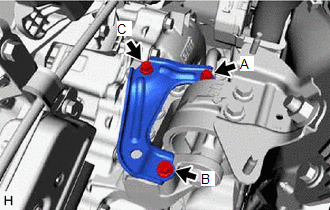
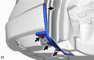
(a) Install the engine mounting insulator sub-assembly LH with the 2 bolts and nut.
Torque:
72 N·m {734 kgf·cm, 53 ft·lbf}
NOTICE:
Temporarily install the bolt (A), and then tighten the 2 bolts and nut in the order of (B), (A) and (C).

|
Bolt |

|
Nut |
|
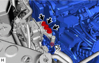
(b) Attach the claw to connect the engine room main wire. |
|
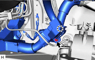
(c) Install the bolt.
Torque:
8.0 N·m {82 kgf·cm, 71 in·lbf}
2. INSTALL ECM
Click here
3. INSTALL ENGINE MOUNTING SPACER
HINT:
Perform this procedure only when replacement of the engine mounting spacer is necessary.
|
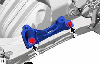
(a) Install the engine mounting spacer to the vehicle body with the 2 bolts. Torque: 72 N·m {734 kgf·cm, 53 ft·lbf} NOTICE: Temporarily install the bolt (A), and then tighten the 2 bolts in the order of (B) and (A). |
|
4. INSTALL ENGINE MOUNTING INSULATOR SUB-ASSEMBLY RH
HINT:
Perform this procedure only when replacement of the engine mounting insulator sub-assembly RH is necessary.
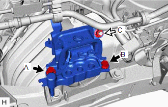
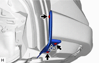
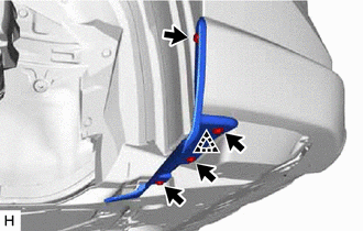
(a) Install the engine mounting insulator sub-assembly RH with the 2 bolts and nut.
Torque:
72 N·m {734 kgf·cm, 53 ft·lbf}
NOTICE:
Temporarily install the bolt (A), and then tighten the 2 bolts and nut in the order of (B), (A) and (C).
|
|
Bolt |
|
|
Nut |
|
(b) Install the bolt to connect the No. 2 ground wire. Torque: 10 N·m {102 kgf·cm, 7 ft·lbf} |
|
|
(c) Attach the clamps to install the radiator reserve tank assembly. |
|
(d) Install the bolt and nut in the order shown in the illustration.
|
|
No. 6 Water By-pass Hose |
|
|
Bolt |

|
Nut |
Torque:
5.0 N·m {51 kgf·cm, 44 in·lbf}
(e) Connect the No. 6 water by-pass hose and attach the clamp.
|
(f) Attach the clamps to connect the suction pipe sub-assembly and air conditioning tube and accessory assembly. |
|
(g) Connect the connector.
5. INSTALL NO. 1 INVERTER RESERVE TANK BRACKET
(a) Install the No. 1 inverter reserve tank bracket with the bolt.
Torque:
14 N·m {143 kgf·cm, 10 ft·lbf}
6. INSTALL ENGINE HANGERS
Click here
7. REMOVE ENGINE ASSEMBLY FROM ENGINE STAND
(a) Remove the engine assembly from the engine stand.
8. INSTALL NO. 1 CRANKSHAFT POSITION SENSOR PLATE
Click here
9. INSTALL FLYWHEEL SUB-ASSEMBLY
Click here
10. INSTALL TRANSMISSION INPUT DAMPER ASSEMBLY
Click here
11. INSTALL HYBRID VEHICLE TRANSAXLE ASSEMBLY
Click here
12. INSTALL FLYWHEEL HOUSING SIDE COVER
Click here
13. INSTALL STARTER HOLE INSULATOR
Click here
14. INSTALL HV AIR CONDITIONING WIRE
|
(a) Attach the guide to install the HV air conditioning wire to the hybrid vehicle transaxle assembly. |
|
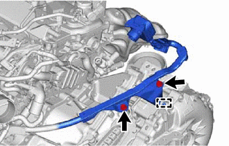
(b) Install the 2 bolts.
Torque:
20 N·m {204 kgf·cm, 15 ft·lbf}
(c) Connect the connector and slide the green-colored lock as shown in the illustration to lock it securely.
CAUTION:
Make sure to wear insulated gloves.
NOTICE:
Make sure that the connector is connected securely.
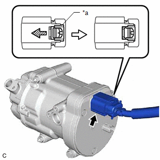
|
*a |
Green-colored Lock |
|
|
Slide |
|
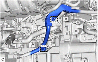
(d) Attach the clamps. |
|
15. INSTALL ENGINE WIRE
(a) Install the engine wire to the engine assembly.
16. INSTALL REAR ENGINE MOUNTING INSULATOR
HINT:
Perform this procedure only when replacement of the rear engine mounting insulator is necessary.
|
(a) Align the hole of the rear engine mounting insulator with the protrusion of the rear engine mounting bracket, slide the rear engine mounting insulator onto the rear engine mounting bracket to align the holes and install the rear engine mounting insulator with the bolt. Torque: 72 N·m {734 kgf·cm, 53 ft·lbf} |
|
(b) Attach the clamp to connect the engine wire.
17. INSTALL WIRING HARNESS CLAMP BRACKET
|
(a) Install the wiring harness clamp bracket with the bolt. Torque: 13 N·m {133 kgf·cm, 10 ft·lbf} |
|
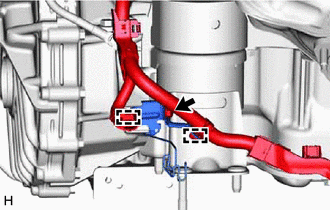
(b) Attach the clamps to connect the engine wire.
18. INSTALL FRONT ENGINE MOUNTING INSULATOR
HINT:
Perform this procedure only when replacement of the front engine mounting insulator is necessary.
Click here
19. INSTALL FRONT FRAME ASSEMBLY
Click here
20. INSTALL FLYWHEEL HOUSING UNDER COVER
(a) Install the flywheel housing under cover to the cylinder block sub-assembly.
21. REMOVE ENGINE HANGERS
(a) Remove the 4 bolts, No. 1 engine hanger and No. 2 engine hanger from the cylinder head sub-assembly and engine mounting bracket RH.
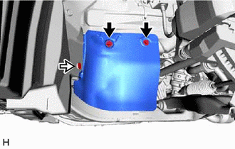
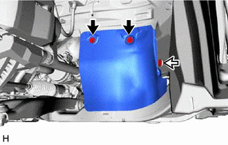
22. INSTALL FUEL DELIVERY GUARD
(a) Install the fuel delivery guard to the engine mounting bracket RH with the bolt.
Torque:
40 N·m {408 kgf·cm, 30 ft·lbf}
23. INSTALL ENGINE ASSEMBLY WITH TRANSAXLE
HINT:
Perform inspection after repair after replacing the engine assembly.
Click here
(a) Set the engine assembly with transaxle on an engine lifter.

|
Attachments |
- |
- |
NOTICE:
- Using height adjustment attachments and plate lift attachments, keep the engine assembly with transaxle level.
- Do not perform any procedures while the engine assembly is suspended because doing so may cause the engine assembly to drop, resulting in injury. However, the engine assembly needs to be suspended when it is installed to or removed from an engine stand.
(b) Operate the engine lifter and install the engine assembly with transaxle to the vehicle.
CAUTION:
Do not raise the engine assembly with transaxle more than necessary. If the engine is raised excessively, the vehicle may also be lifted up.
NOTICE:
- Make sure that the engine assembly with transaxle is clear of all wiring and hoses.
- While raising the engine assembly with transaxle into the vehicle, do not allow it to contact the vehicle.
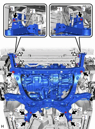
(c) Install the front bumper extension sub-assembly LH and front bumper extension sub-assembly RH to the front frame assembly and vehicle body with the 2 bolts (A), 2 bolts (B) and 4 nuts.
Torque:
Bolt (A) :
135 N·m {1377 kgf·cm, 100 ft·lbf}
Bolt (B) :
9.5 N·m {97 kgf·cm, 84 in·lbf}
Nut :
12.5 N·m {127 kgf·cm, 9 ft·lbf}
|
*1 |
Front Bumper Extension Sub-assembly LH |
|
*2 |
Front Bumper Extension Sub-assembly RH |
|
*3 |
Rear Front Suspension Member Brace LH |
|
*4 |
Rear Front Suspension Member Brace RH |
|
|
Bolt |
|
|
Nut |
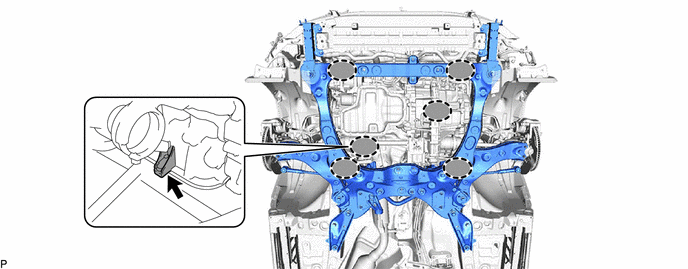
(d) Install the rear front suspension member brace LH and rear front suspension member brace RH to the front frame assembly and vehicle body with the 2 bolts (C) and 4 bolts (D).
Torque:
Bolt (C) :
135 N·m {1377 kgf·cm, 100 ft·lbf}
Bolt (D) :
60 N·m {612 kgf·cm, 44 ft·lbf}
|
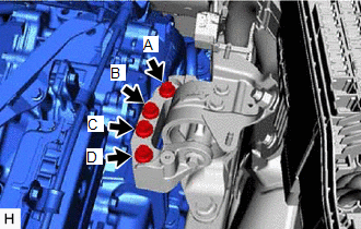
(e) Install the engine mounting insulator sub-assembly LH to the hybrid vehicle transaxle assembly with the 4 bolts. Torque: 42 N·m {428 kgf·cm, 31 ft·lbf} NOTICE: Tighten the 4 bolts in the order of (A), (C), (B) and (D). |
|
|
(f) Install the engine mounting stay LH to the engine mounting insulator sub-assembly LH with the 3 bolts. Torque: 8.0 N·m {82 kgf·cm, 71 in·lbf} NOTICE: Temporarily install the bolt (A), and then tighten the 3 bolts in the order of (B), (C) and (A). |
|
(g) Install the engine mounting insulator sub-assembly RH to the engine mounting bracket RH with the 3 bolts and nut.
Torque:
Bolt :
72 N·m {734 kgf·cm, 53 ft·lbf}
Nut :
42 N·m {428 kgf·cm, 31 ft·lbf}
|
|
Bolt |
|
|
Nut |
24. CONNECT STEERING INTERMEDIATE SHAFT ASSEMBLY
Click here
25. INSTALL FRONT DRIVE SHAFT ASSEMBLY LH
Click here
26. INSTALL FRONT DRIVE SHAFT ASSEMBLY RH
Click here
27. CONNECT FRONT LOWER NO. 1 SUSPENSION ARM SUB-ASSEMBLY LH
Click here
28. CONNECT FRONT LOWER NO. 1 SUSPENSION ARM SUB-ASSEMBLY RH
HINT:
Use the same procedure described for the LH side.
29. CONNECT TIE ROD ASSEMBLY LH
Click here
30. CONNECT TIE ROD ASSEMBLY RH
HINT:
Use the same procedure described for the LH side.
31. CONNECT FRONT STABILIZER LINK ASSEMBLY LH
Click here
32. CONNECT FRONT STABILIZER LINK ASSEMBLY RH
HINT:
Use the same procedure described for the LH side.
33. CONNECT FRONT SPEED SENSOR LH
Click here
34. CONNECT FRONT SPEED SENSOR RH
HINT:
Use the same procedure described for the LH side.
35. INSTALL FRONT AXLE SHAFT NUT LH
Click here
36. INSTALL FRONT AXLE SHAFT NUT RH
HINT:
Use the same procedure described for the LH side.
37. STAKE FRONT AXLE SHAFT NUT LH
Click here
38. STAKE FRONT AXLE SHAFT NUT RH
HINT:
Use the same procedure described for the LH side.
39. INSTALL FRONT EXHAUST PIPE ASSEMBLY
Click here
40. INSTALL FRONT FLOOR COVER RH
(a) Attach the clips to install the front floor cover RH.
|
|
Bolt |
|
|
Screw |
|
|
Clip |
(b) Install the 2 bolts, 3 screws and clip.
Torque:
Bolt :
7.5 N·m {76 kgf·cm, 66 in·lbf}
41. INSTALL FRONT FLOOR COVER LH
(a) Attach the clips to install the front floor cover LH.
|
|
Bolt |
|
|
Screw |
|
|
Clip |
(b) Install the 2 bolts, 4 screws and clip.
Torque:
Bolt :
7.5 N·m {76 kgf·cm, 66 in·lbf}
42. INSTALL ENGINE UNDER COVER HEAT INSULATOR
(a) Install the engine under cover heat insulator with the 2 clips.
43. CONNECT WIRE HARNESS
|
(a) Install the 2 bolts to connect the ground wires. Torque: 10 N·m {102 kgf·cm, 7 ft·lbf} |
|
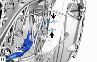
(b) Attach the clamp.
(c) Attach the claw to connect the wire harness to the engine room relay block and junction block assembly.
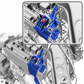
|
|
Nut |
|
|
Connector |
(d) Connect the connectors to the engine room relay block and junction block assembly.
(e) Install the nut to the engine room relay block and junction block assembly.
Torque:
8.0 N·m {82 kgf·cm, 71 in·lbf}
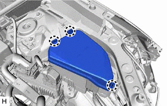
|
(f) Attach the claws and remove the No. 2 relay block cover. |
|
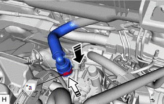
44. CONNECT NO. 5 INVERTER COOLING HOSE
(a) Connect the No. 5 inverter cooling hose to the motor cooling cooler, and slide the clip to secure the hose.
NOTICE:
- Check that there is no excessive deformation of the motor cooling cooler pipe before connecting the No. 5 inverter cooling hose.
- If the motor cooling cooler pipe is deformed replace it because using a deformed pipe can cause coolant leakage.
- When connecting the No. 5 inverter cooling hose, do not apply excessive force to the motor cooling cooler pipe.
- Align the direction of the claw on the clip with the paint mark on the hose.
- Make sure the No. 5 inverter cooling hose is securely inserted to the stopper.
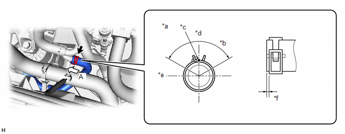
|
*a |
View A |
*b |
120° |
|
*c |
Paint Mark |
*d |
Upper Side |
|
*e |
Front Side |
*f |
2 to 7 mm (0.0787 to 0.276 in.) |
45. CONNECT SUCTION HOSE SUB-ASSEMBLY
Click here
46. CONNECT NO. 1 COOLER REFRIGERANT DISCHARGE HOSE
Click here
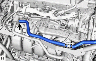
47. CONNECT NO. 2 RADIATOR HOSE
(a) Connect the No. 2 radiator hose to the water inlet, and slide the clip to secure the hose.
NOTICE:
- Align the direction of the claw on the clip with the paint mark on the hose.
- Make sure the No. 2 radiator hose is securely inserted to the stopper.
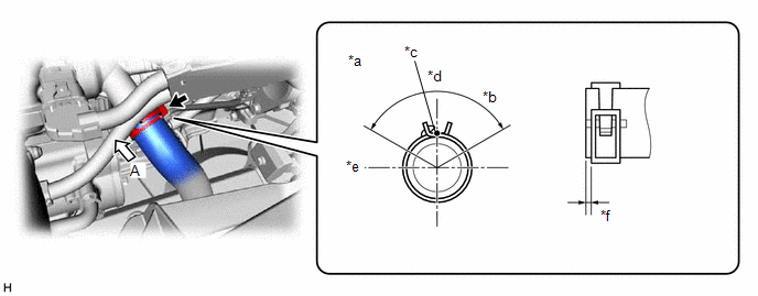
|
*a |
View A |
*b |
120° |
|
*c |
Paint Mark |
*d |
Upper Side |
|
*e |
RH Side |
*f |
2 to 7 mm (0.0787 to 0.276 in.) |
48. CONNECT NO. 1 RADIATOR HOSE
(a) Connect the No. 1 radiator hose to the water outlet, and slide the clip to secure the hose.
NOTICE:
- Align the direction of the claw on the clip with the paint mark on the hose.
- Make sure the No. 1 radiator hose is securely inserted to the stopper.
(b) Attach the clamp.
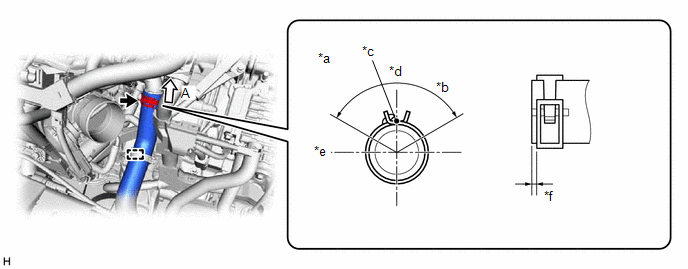
|
*a |
View A |
*b |
120° |
|
*c |
Paint Mark |
*d |
Front Side |
|
*e |
RH Side |
*f |
2 to 7 mm (0.0787 to 0.276 in.) |
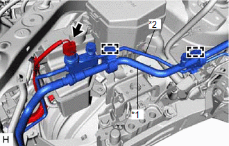
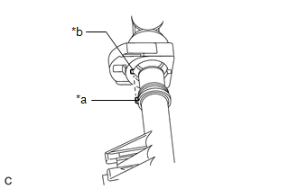
49. CONNECT INLET HEATER WATER HOSE
|
(a) Align the protrusions of the inlet heater water hose connector with the cutouts in the flow shutting valve (water by-pass hose assembly) and securely insert the inlet heater water hose connector to the stopper of the pipe. |
|
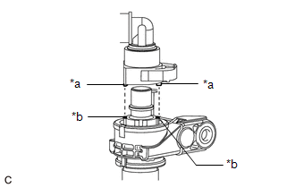
(b) Push in the retainer.
|
*a |
Retainer |

|
Push |

|
Push in |
(c) Check that the flow shutting valve (water by-pass hose assembly) and inlet heater hose connector are securely connected by pulling on them.
50. CONNECT OUTLET HEATER WATER HOSE
|
(a) Align the protrusion of the No. 2 water by-pass pipe sub-assembly with the cutout in the outlet heater water hose connector and securely insert the outlet heater water hose connector to the stopper of the pipe. |
|
(b) Push in the retainer.
|
*a |
Retainer |
|
|
Push |
|
|
Push in |
(c) Check that the No. 2 water by-pass pipe sub-assembly and outlet heater hose connector are securely connected by pulling on them.
51. CONNECT FUEL TUBE SUB-ASSEMBLY
(a) Connect the fuel tube sub-assembly.
|
(1) Connect the fuel tube sub-assembly to the fuel pipe. Click here
|
|
|
(b) Install the No. 1 fuel pipe clamp to the fuel tube connector. Click here
|
|
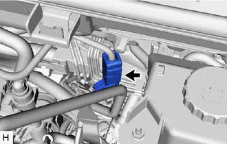
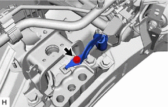
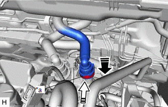
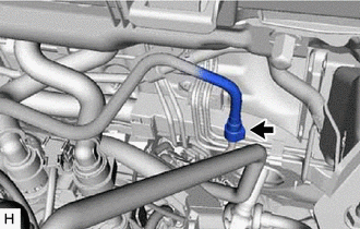
52. CONNECT NO. 1 FUEL VAPOR FEED HOSE
|
(a) Connect the No. 1 fuel vapor feed hose to the purge VSV. |
|
(b) Attach the clamp.
53. INSTALL NO. 5 WATER BY-PASS HOSE
(a) Install the No. 5 water by-pass hose to the No. 3 water by-pass pipe and radiator assembly, and slide the clips to secure the hose.
NOTICE:
- Align the direction of the claw on the clip with the paint mark on the hose.
- Make sure the No. 5 water by-pass hose is securely inserted to the stopper.
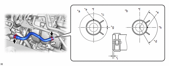
|
*a |
View A |
*b |
View B |
|
*c |
360° |
*d |
120° |
|
*e |
Paint Mark |
*f |
Upper Side |
|
*g |
Front Side |
*h |
Rear Side |
|
*i |
2 to 7 mm (0.0787 to 0.276 in.) |
- |
- |
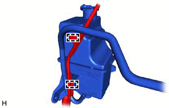
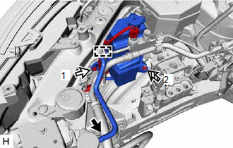
54. INSTALL INVERTER RESERVE TANK ASSEMBLY
(a) Connect the No. 2 inverter cooling hose and No. 5 inverter cooling hose to the inverter reserve tank assembly, and slide the clips to secure the hoses.
NOTICE:
- Align the direction of the claw on the clip with the paint mark on the hose.
- Make sure the No. 2 inverter cooling hose and No. 5 inverter cooling hose are securely inserted to the stopper.
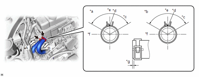
|
*a |
View A |
*b |
View B |
|
*c |
120° |
*d |
Paint Mark |
|
*e |
Upper Side |
*f |
RH Side |
|
*g |
2 to 7 mm (0.0787 to 0.276 in.) |
- |
- |
|
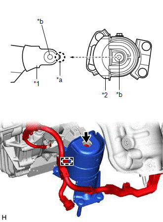
(b) Fit the pin of the inverter reserve tank assembly into grommet as shown in the illustration. |
|
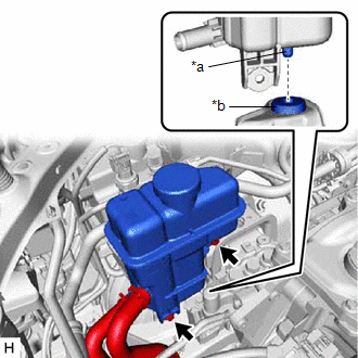
(c) Install the inverter reserve tank assembly with the 2 bolts.
Torque:
5.0 N·m {51 kgf·cm, 44 in·lbf}
55. INSTALL INVERTER WITH CONVERTER ASSEMBLY
Click here
56. INSTALL AIR CLEANER ASSEMBLY WITH AIR CLEANER HOSE
Click here
57. INSTALL INLET AIR CLEANER ASSEMBLY
Click here
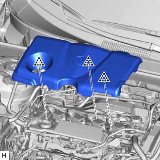
58. INSTALL NO. 1 ENGINE COVER SUB-ASSEMBLY
|
(a) Attach the clips to install the No. 1 engine cover sub-assembly. NOTICE:
|
|
59. INSTALL FRONT BUMPER NO. 2 REINFORCEMENT
Click here
60. INSTALL FRONT LOWER BUMPER ABSORBER
|
(a) Attach the claws to install the front lower bumper absorber. |
|
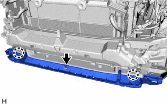
(b) Install the clip.
61. INSTALL HEADLIGHT ASSEMBLY LH
-
for Triple Beam Headlight:
Click here
-
for Single Beam Headlight:
Click here
62. INSTALL FRONT BUMPER ASSEMBLY
Click here
63. INSTALL FRONT FENDER APRON SEAL LH
(a) Install the front fender apron seal LH with the 2 bolts and clip.
Torque:
7.5 N·m {76 kgf·cm, 66 in·lbf}
|
|
Bolt |
|
|
Clip |
64. INSTALL FRONT FENDER APRON SEAL RH
(a) Install the front fender apron seal RH with the 2 bolts and clip.
Torque:
7.5 N·m {76 kgf·cm, 66 in·lbf}
|
|
Bolt |
|
|
Clip |
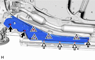
65. INSTALL NO. 2 ENGINE UNDER COVER ASSEMBLY
(a) Install the No. 2 engine under cover assembly with the 2 bolts, 2 screws and 6 clips.
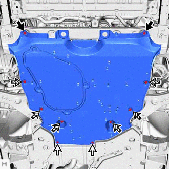
|
|
Bolt |
|
|
Screw |
|
|
Clip |
Torque:
Bolt :
7.5 N·m {76 kgf·cm, 66 in·lbf}
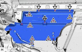
66. INSTALL NO. 1 ENGINE UNDER COVER
(a) for Type A:
(1) Attach the guide to install the No. 1 engine under cover.
(2) Install the 2 bolts and 6 screws.
Torque:
Bolt :
7.5 N·m {76 kgf·cm, 66 in·lbf}
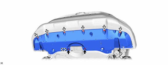
|
|
Bolt |
|
Screw |
(b) for Type B:
(1) Attach the guide to install the No. 1 engine under cover.
(2) Install the 2 bolts and 10 screws. (Short Type Front Fender Front Splash Shield)
Torque:
Bolt :
7.5 N·m {76 kgf·cm, 66 in·lbf}
(3) Install the 2 bolts and 8 screws. (Long Type Front Fender Front Splash Shield)
Torque:
Bolt :
7.5 N·m {76 kgf·cm, 66 in·lbf}
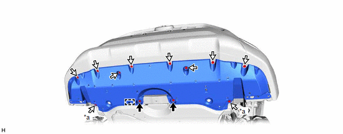
|
*a |
Short Type Front Fender Front Splash Shield |
- |
- |
|
|
Bolt |
|
Screw |
67. INSTALL FRONT FENDER FRONT SPLASH SHIELD LH
(a) for Short Type:
|
(1) Attach the clip to install the front fender front splash shield LH. |
|
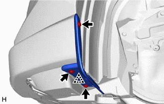
(2) Install the 3 screws.
(b) for Long Type:
|
(1) Attach the clip to install the front fender front splash shield LH. |
|
(2) Install the 4 screws.
68. INSTALL FRONT FENDER FRONT SPLASH SHIELD RH
(a) for Short Type:
|
(1) Attach the clip to install the front fender front splash shield RH. |
|
(2) Install the 3 screws.
(b) for Long Type:
|
(1) Attach the clip to install the front fender front splash shield RH. |
|
(2) Install the 4 screws.
69. INSTALL SERVICE PLUG GRIP
Click here
70. INSTALL BATTERY SERVICE HOLE COVER
Click here
71. CONNECT CABLE TO NEGATIVE AUXILIARY BATTERY TERMINAL
Click here
72. INSTALL BATTERY HOLE COVER
Click here
73. INSTALL REAR NO. 2 FLOOR BOARD
Click here
74. INSTALL DECK BOARD ASSEMBLY
Click here
75. INSPECT SHIFT LEVER POSITION
Click here
76. ADJUST SHIFT LEVER POSITION
Click here
77. ADD ENGINE OIL
Click here
78. ADD HYBRID TRANSAXLE FLUID
Click here
79. INSPECT HYBRID TRANSAXLE FLUID
Click here
80. CHARGE AIR CONDITIONING SYSTEM WITH REFRIGERANT
Click here
81. ADD ENGINE COOLANT (for Engine)
Click here
82. WARM UP COMPRESSOR
Click here
83. INSPECT FOR ENGINE OIL LEAK
Click here
84. INSPECT FOR COOLANT LEAK (for Engine)
Click here
85. INSPECT FOR REFRIGERANT LEAK
Click here
86. INSPECT FOR FUEL LEAK
Click here
87. INSPECT FOR EXHAUST GAS LEAK
Click here
88. CHECK ENGINE OIL LEVEL
Click here
89. INSPECT ENGINE COOLANT LEVEL IN RESERVOIR
Click here
90. INSTALL FRONT WHEELS
Click here
91. ALIGN FRONT WHEELS FACING STRAIGHT AHEAD
92. INSPECT AND ADJUST FRONT WHEEL ALIGNMENT
Click here
93. INSPECT THROTTLE BODY WITH MOTOR ASSEMBLY
Click here
94. INSPECT IGNITION TIMING
Click here
95. INSPECT ENGINE IDLE SPEED
Click here
96. INSPECT CO/HC
Click here
97. CHECK SPEED SENSOR SIGNAL
Click here
|
|
|