| Last Modified: 01-30-2024 | 6.11:8.1.0 | Doc ID: RM1000000021PPH |
| Model Year Start: 2022 | Model: RAV4 HV | Prod Date Range: [12/2021 - 10/2022] |
| Title: A25A-FXS (ENGINE CONTROL): ECM: REMOVAL; 2022 MY RAV4 HV [12/2021 - 10/2022] | ||
REMOVAL
CAUTION / NOTICE / HINT
The necessary procedures (adjustment, calibration, initialization or registration) that must be performed after parts are removed and installed, or replaced during ECM removal/installation are shown below.
Necessary Procedures After Parts Removed/Installed/Replaced
|
Replaced Part or Performed Procedure |
Necessary Procedure |
Effect/Inoperative Function when Necessary Procedure not Performed |
Link |
|---|---|---|---|
|
Auxiliary battery terminal is disconnected/reconnected |
Perform steering sensor zero point calibration |
Lane control system |
|
|
Parking support brake system (for HV model) |
|||
|
Pre-collision system |
|||
|
Memorize steering angle neutral point |
Parking assist monitor system |
||
|
Panoramic view monitor system (for HV model) |
|||
|
Reset back door close position |
Power back door system (for HV model) |
||
|
Back door lock initialization |
Power door lock control system |
||
|
ECM |
Perform Vehicle Identification Number (VIN) registration |
DTC P063051 is output |
|
|
Grille shutter switch specification infomation |
Vehicle control history (RoB) [X260E] is stored |
NOTICE:
- If the ECM has been struck or dropped, replace it.
- Perform Vehicle Identification Number (VIN) registration when replacing the ECM.
-
After the ignition switch is turned off, the radio and display receiver assembly records various types of memory and settings. As a result, after turning the ignition switch off, be sure to wait for the time specified in the following table before disconnecting the cable from the negative (-) auxiliary battery terminal.
Waiting Time before Disconnecting Cable from Negative (-) Auxiliary Battery Terminal
System Name
See Procedure
Vehicle enrolled in Toyota Audio Multimedia system or safety connect system
6 minutes
Vehicle not enrolled in Toyota Audio Multimedia system and safety connect system
1 minute
PROCEDURE
1. PRECAUTION (for LITHIUM-ION BATTERY)
HV battery learning values are stored in the battery ECU assembly and ECM and are used to detect malfunctions and illuminate the hybrid battery indicator light in the combination meter assembly. When either of these ECUs is replaced, the new ECU receives the HV battery learning values from the other ECU and stores them.
NOTICE:
- Do not replace the battery ECU assembly and ECM at the same time as the HV battery learning values will be lost. However, if it is necessary to replace both ECUs at the same time, replace them by following the procedure below.
- Do not replace the battery ECU assembly or ECM with a used one from another vehicle.
(a) Procedure when replacing both battery ECU assembly and ECM:
(1) Disconnect the cable from the negative (-) auxiliary battery terminal.
(2) Replace either ECU.
(3) Connect the cable to the negative (-) auxiliary battery terminal.
(4) Turn the power switch on (READY) and wait for 5 minutes or more.
(5) Turn the power switch off and disconnect the cable from the negative (-) auxiliary battery terminal.
(6) Replace the other ECU.
(7) Connect the cable to the negative (-) auxiliary battery terminal.
(8) Check that the power switch can be turned on (READY).
HINT:
If the battery ECU assembly and ECM are replaced at the same time without following the above procedure, replace either the battery ECU assembly and ECM with its original one and then replace it again by following the above procedure. If the correct procedure is not followed, perform the procedure again from the beginning.
2. REMOVE DECK BOARD ASSEMBLY
3. REMOVE REAR NO. 2 FLOOR BOARD
4. REMOVE BATTERY HOLE COVER
5. DISCONNECT CABLE FROM NEGATIVE AUXILIARY BATTERY TERMINAL
6. REMOVE ECM
|
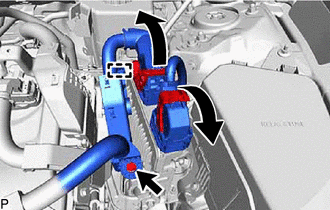
(a) Push in the locks on the 2 levers, raise the 2 levers, and disconnect the 2 ECM connectors. NOTICE: After disconnecting the ECM connectors, make sure that dirt, water or other foreign matter does not contact the connecting parts of the ECM connectors. |
|
(b) Remove the bolt and detach the clamp.
|
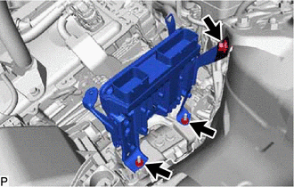
(c) Remove the 2 nuts and bolt. |
|
(d) Remove the ECM.
NOTICE:
If the ECM has been struck or dropped, replace it.
7. REMOVE NO. 1 ECM BRACKET
|
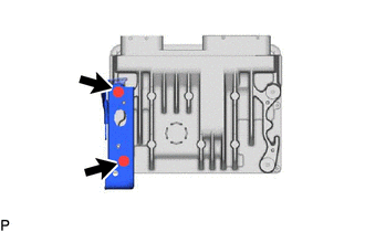
(a) Remove the 2 screws and No. 1 ECM bracket from the ECM. |
|
8. REMOVE NO. 2 ECM BRACKET
|
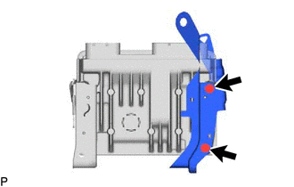
(a) Remove the 2 screws and No. 2 ECM bracket from the ECM. |
|
|
|
|
![2022 - 2024 MY RAV4 RAV4 HV [12/2021 - ]; PRE-COLLISION: PRE-COLLISION SYSTEM: INITIALIZATION](/t3Portal/stylegraphics/info.gif)


