- Perform reset memory
- Input transaxle compensation code into ECM
- Perform road test to allow ECM to learn
| Last Modified: 01-30-2024 | 6.11:8.1.0 | Doc ID: RM100000002591T |
| Model Year Start: 2023 | Model: RAV4 | Prod Date Range: [10/2022 - 10/2023] |
| Title: GF2A (TRANSFER / 4WD / AWD): TRANSFER CASE REAR OIL SEAL: REPLACEMENT; 2023 MY RAV4 RAV4 HV [10/2022 - 10/2023] | ||
REPLACEMENT
CAUTION / NOTICE / HINT
The necessary procedures (adjustment, calibration, initialization, or registration) that must be performed after parts are removed and installed, or replaced during the rear transfer case oil seal removal/installation are shown below.
Necessary Procedure After Parts Removed/Installed/Replaced
|
Replacement Part or Procedure |
Necessary Procedure |
Effect/Inoperative when not Performed |
Link |
|---|---|---|---|
| *: When performing learning using the Techstream. | |||
|
Disconnect cable from negative battery terminal |
Drive the vehicle until stop and start control is permitted (approximately 5 to 60 minutes) |
Stop and start system |
|
|
Perform steering sensor zero point calibration |
Lane control system |
||
|
Parking support brake system* |
|||
|
Pre-collision system |
|||
|
Reset back door close position |
Power back door system |
||
|
Back door lock initialization |
Power door lock control system |
||
|
Automatic transaxle assembly |
|
|
|
|
Automatic transaxle fluid |
ATF thermal degradation estimate reset |
The value of the Data List item "ATF Thermal Degradation Estimate" is not estimated correctly |
|
|
Front electro magnetic control clutch sub-assembly |
Disconnect system function check |
Dynamic torque vectoring AWD system |
|
|
Front wheel alignment adjustment |
|
|
|
|
Suspension, tires, etc. |
Television camera assembly optical axis (Back camera position setting) |
Parking assist monitor system |
|
|
Parking assist ECU initialization |
Panoramic view monitor system (for Gasoline model) |
||
|
Panoramic view monitor system (for HV model) |
|||
NOTICE:
After the ignition switch is turned off, the navigation system requires approximately a minute to record various types of memory and settings. As a result, after turning the ignition switch off, wait a minute or more before disconnecting the cable from the negative (-) battery terminal.
Waiting Time before Disconnecting Cable from Negative (-) Battery Terminal
|
System Name |
See Procedure |
|---|---|
|
Vehicle enrolled in Toyota Audio Multimedia system or safety connect system |
6 minutes |
|
Vehicle not enrolled in Toyota Audio Multimedia system and safety connect system |
1 minute |
CAUTION:
-
The engine assembly with transaxle is very heavy. Be sure to follow the procedure described in the repair manual, or the engine lifter may suddenly drop or the engine assembly with transaxle may fall off the engine lifter.
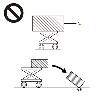
*a
An Object Exceeding Weight Limit of Engine Lifter
-
To prevent burns, do not touch the engine, exhaust manifold or other high temperature components while the engine is hot.
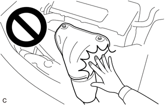
-
The automatic transaxle assembly is very heavy. Be sure to follow the procedure described in the repair manual, or the transmission jack may suddenly drop.
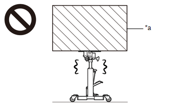
*a
An Object Exceeding Weight Limit of Transmission Jack
PROCEDURE
1. REMOVE TRANSFER ASSEMBLY
2. REMOVE TRANSFER AND TRANSAXLE SETTING STUD BOLT
3. SECURE TRANSFER ASSEMBLY
4. INSPECT TOTAL PRELOAD
5. REMOVE OUTPUT SHAFT COMPANION FLANGE NUT
6. REMOVE OUTPUT SHAFT COMPANION FLANGE SUB-ASSEMBLY
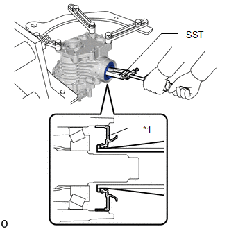
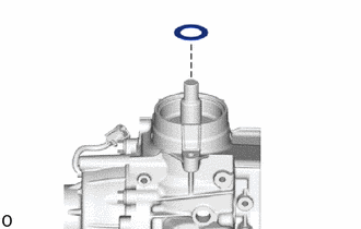
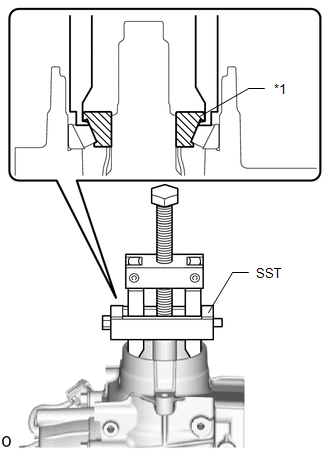
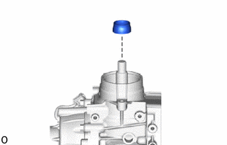
7. REMOVE NO. 2 TRANSFER CASE OIL SEAL
|
(a) Using SST, remove the No. 2 transfer case oil seal from the transfer case. SST: 09308-00010 NOTICE: Do not damage the No. 2 transfer case oil seal press-fit surface. |
|
|
(b) Remove the spacer. |
|
|
(c) Using SST, remove the rear drive pinion bearing (inner race). SST: 09556-40010 |
|
|
(d) Remove the transfer pinion bearing spacer. |
|
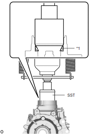
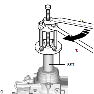
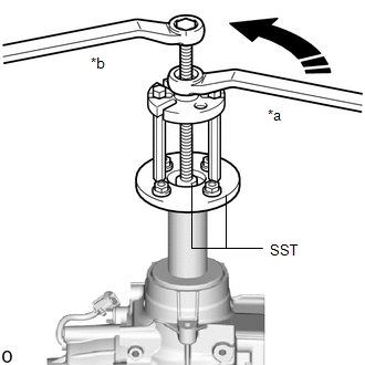
(e) Using SST, remove the rear drive pinion bearing (outer race).
SST: 09950-40011
09951-04010
09952-04010
09953-04010
09954-04010
09957-04010
SST: 09506-42030
SST: 09955-04160
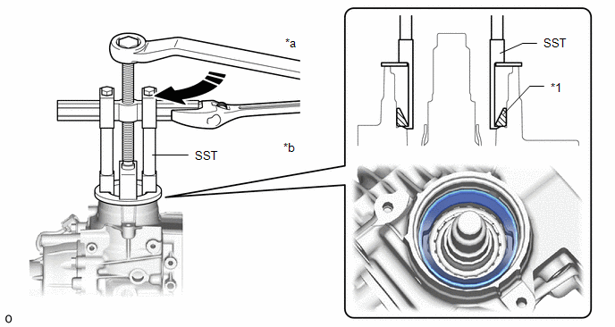
|
*1 |
Rear Drive Pinion Bearing (Outer Race) |
- |
- |
|
*a |
Turn |
*b |
Hold |
8. INSTALL NO. 2 TRANSFER CASE OIL SEAL
|
(a) Using SST and a press, install the rear drive pinion bearing (outer race). SST: 09506-42020 |
|
|
(b) Install a new transfer pinion bearing spacer. |
|
(c) Temporarily install the output shaft companion flange sub-assembly.
|
(d) Using SST, install the rear drive pinion bearing (inner race). SST: 09950-30012 09951-03010 09953-03010 09954-03010 09955-03030 SST: 09956-03090 |
|
|
(e) Using SST, remove the output shaft companion flange sub-assembly. SST: 09950-30012 09951-03010 09953-03010 09954-03010 09955-03030 SST: 09956-03090 |
|
|
(f) install the spacer. |
|
(g) Apply a small amount of MP grease to the lip of a new No.2 transfer case oil seal.
(h) Using SST, install a new No. 2 transfer case oil seal to the transfer case.
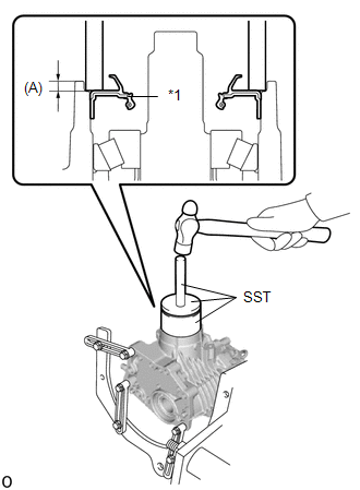
|
*1 |
No. 2 Transfer Case Oil Seal |
SST: 09554-42010
SST: 09950-60021
09951-01030
SST: 09950-70010
09951-07100
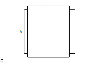
Drive in depth (A):
3.9 to 4.9 mm (0.154 to 0.193 in.)
NOTICE:
Do not damage the No. 2 transfer case oil seal press-fit surface.
HINT:
Press using the A surface.
9. INSTALL OUTPUT SHAFT COMPANION FLANGE SUB-ASSEMBLY
10. INSPECT TOTAL PRELOAD
11. INSTALL OUTPUT SHAFT COMPANION FLANGE NUT
12. REMOVE TRANSFER ASSEMBLY
13. INSTALL TRANSFER AND TRANSAXLE SETTING STUD BOLT
14. INSTALL TRANSFER ASSEMBLY
|
|
|
![2023 MY RAV4 [10/2022 - 10/2023]; PARK ASSIST / MONITORING: PARKING SUPPORT BRAKE SYSTEM (for Gasoline Model): CALIBRATION](/t3Portal/stylegraphics/info.gif)
