| 
                           Last Modified: 05-08-2025 | 
                        6.11:8.1.0  | 
                        
                           Doc ID: RM1000000026QHH | 
                      
                     
                        | 
                           Model Year Start: 2023 | 
                        
                           Model: RAV4 HV | 
                        
                           Prod Date Range: [10/2022 - 10/2023] | 
                      
                     
                        | 
                           Title: FRONT SUSPENSION: FRONT SUSPENSION MEMBER (for HV Model): REMOVAL; 2023 MY RAV4 HV [10/2022 - 10/2023] | 
                      
                   
                  REMOVAL
                   
                  CAUTION / NOTICE / HINT
                  The necessary procedures (adjustment, calibration, initialization, or registration) that must be performed after parts are removed and installed, or replaced during front frame assembly removal/installation are shown below. 
                  Necessary Procedures After Parts Removed/Installed/Replaced


                           | 
                               Replaced Part or Performed Procedure 
                            | 
                           
                               Necessary Procedure 
                            | 
                           
                               Effect/Inoperative Function when Necessary Procedure not Performed 
                            | 
                           
                               Link 
                            | 


                           | 
                               Auxiliary battery terminal is disconnected/reconnected 
                            | 
                           
                               Perform steering sensor zero point calibration 
                            | 
                           
                               Lane control system 
                            | 


                            | 
                         
                        
                           | 
                               Parking support brake system (for HV model)* 
                            | 
                         
                        
                           | 
                               Pre-collision system 
                            | 
                         
                        
                           | 
                               Reset back door close position 
                            | 
                           
                               Power back door system (for HV model) 
                            | 


                            | 
                         
                        
                           | 
                               Back door lock initialization 
                            | 
                           
                               Power door lock control system 
                            | 


                            | 
                         
                        
                           | 
                               ECM 
                            | 
                           
                               Perform Vehicle Identification Number (VIN) registration 
                            | 
                           
                               DTC P063051 is output 
                            | 


                            | 
                         
                        
                           | 
                               Grille shutter switch specification infomation 
                            | 
                           
                               Vehicle control history (RoB) [X260E] is stored 
                            | 


                            | 


                                    - 
Air fuel ratio sensor (sensor 1)
 
                                    - 
Air fuel ratio sensor (sensor 2)
 
                                    - 
Gas leak from exhaust system is repaired


                            | 
                           
                               Inspection after repair 
                            | 


                                    - 
Poor idle, etc.
 
                                    - 
Engine start function, etc.


                            | 


                            | 
                         
                        
                           | 
                               Inverter with converter assembly 
                            | 
                           
                               Resolver learning 
                            | 


                                    - 
DTCs are stored
 
                                    - 
Slight vibration at a vehicle speed of 5 km/h (3 mph) or less
 
                                    - 
Shock or vibration during acceleration


                            | 
                           
                               for AWD with NICKEL METAL HYDRIDE BATTERY:


                              for LITHIUM-ION BATTERY:


                            | 
                         
                        
                           | 
                               Hybrid vehicle transaxle assembly 
                            | 


                                    - 
Resolver learning
 
                                    - 
Initialize resolver


                            | 
                         
                        
                           | 
                               Front wheel alignment adjustment 
                            | 


                                    - 
Perform "Reset Memory"
 
                                    - 
Perform "Calibration"


                            | 


                                    - 
DTCs are stored
 
                                    - 
ABS warning light illuminates
 
                                    - 
Brake system warning light (yellow indicator) illuminates
 
                                    - 
Slip indicator light illuminates
 
                                    - 
Brake control disabled or malfunctions (brake drag, etc.)


                            | 


                            | 
                         
                        
                           | 
                               Rack and pinion power steering gear assembly 
                            | 
                           
                              
                                 for Type A:
                                 
                                    - 
Perform power steering ECU initial setting


                            | 


                                    - 
DTCs are output
 
                                    - 
EPS warning light  illuminates


                            | 


                            | 


                                 for Type B:
                                 
                                    - 
Perform torque sensor zero point calibration
 
                                    - 
Assist map writing


                            | 


                                    - 
DTCs are output
 
                                    - 
EPS warning light  illuminates


                            | 


                            | 
                         
                        
                           | 
                               Front bumper assembly (Including removal and installation) 
                            | 
                           
                               Front television camera view adjustment 
                            | 
                           
                               Panoramic view monitor system (for HV model) 
                            | 


                            | 
                         
                        
                           | 
                               Suspension, tires, etc. 
                            | 
                           
                               Television camera assembly optical axis (Back camera position setting) 
                            | 
                           
                               Parking assist monitor system 
                            | 


                            | 


                                    - 
Parking assist ECU initialization
 
                                    - 
Adjust steering angle


                            | 
                           
                               Panoramic view monitor system (for HV model) 
                            | 


                            | 


                     NOTICE: 
                     
                        - 
After the ignition switch is turned off, the audio and visual system records various types of memory and settings. As a result, after turning the ignition switch off, make sure to wait at least 2 minutes before disconnecting the cable from the negative (-) auxiliary battery terminal.
 
                        - 
When the cable is disconnected from the negative (-) auxiliary battery terminal and the security lock setting has been enabled, multi-display operations will be disabled upon next startup unless the password is entered. Be sure to check the security lock setting before disconnecting the cable from the negative (-) auxiliary battery terminal.
 
                        - 
This procedure includes the removal of small-head bolts. Refer to Small-Head Bolts of Basic Repair Hint to identify the small-head bolts.
Click here


                  PROCEDURE
                   
                  1. REMOVE ENGINE ASSEMBLY WITH TRANSAXLE 
                  Click here


                  2. REMOVE FUEL DELIVERY GUARD 
                  Click here


                  3. INSTALL ENGINE HANGERS 
                  Click here


                  4. REMOVE STEERING GEAR HEAT INSULATOR 
                  Click here


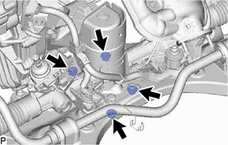
                  5. DISCONNECT WIRE HARNESS 
                  Click here


                  6. REMOVE FRONT FRAME ASSEMBLY 


                           | 
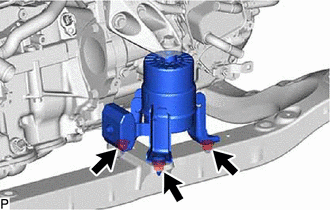
                               (a) Remove the 3 nuts and separate the front engine mounting insulator from the front frame assembly. 
                            | 
                           
                              
                            | 


                           | 
                               (b) Remove the 4 nuts and separate the rear engine mounting insulator from the front frame assembly. 
                            | 
                           
                              
                            | 


                  7. REMOVE FRONT STABILIZER BAR WITH BRACKET 
                  Click here


                  8. REMOVE RACK AND PINION POWER STEERING GEAR ASSEMBLY 
                  Click here


                  9. REMOVE FRONT LOWER NO. 1 SUSPENSION ARM SUB-ASSEMBLY LH 


                           | 
                               (a) Remove the 3 bolts, nut and front lower No. 1 suspension arm sub-assembly LH from the front frame assembly. 
                              NOTICE: 
                              Because the nut has its own stopper, do not turn the nut. Loosen the bolt with the nut secured. 
                            | 
                           
                              
                            | 


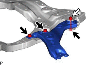
                  (b) Remove the front lower arm bushing stopper from the front lower No. 1 suspension arm sub-assembly. 
                   
                  10. REMOVE FRONT LOWER NO. 1 SUSPENSION ARM SUB-ASSEMBLY RH 
                  HINT: 
                  Perform the same procedure as for the LH side. 
                   
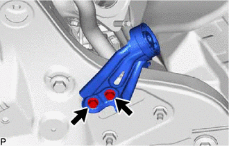
                  11. REMOVE NO. 2 EXHAUST PIPE SUPPORT BRACKET 


                           | 
                               (a) Remove the 2 bolts and No. 2 exhaust pipe support bracket from the front frame assembly. 
                            | 
                           
                              
                            | 


                |