| Last Modified: 11-18-2025 | 6.11:8.1.0 | Doc ID: RM1000000026SV4 |
| Model Year Start: 2023 | Model: RAV4 HV | Prod Date Range: [10/2022 - ] |
| Title: PARK ASSIST / MONITORING: PANORAMIC VIEW MONITOR SYSTEM (for HV Model): C162287,C168187,C168E87,C169D87; Rear Camera Image Signal Missing Message; 2023 - 2025 MY RAV4 HV [10/2022 - ] | ||
|
DTC |
C162287 |
Rear Camera Image Signal Missing Message |
|
DTC |
C168187 |
Front Camera Image Signal Missing Message |
|
DTC |
C168E87 |
Side Camera (Left) Image Signal Missing Message |
|
DTC |
C169D87 |
Side Camera (Right) Image Signal Missing Message |
DESCRIPTION
These DTCs are stored when the parking assist ECU performs a self-diagnosis and detects that the input/output signal line of a camera is open.
|
DTC No. |
Detection Item |
DTC Detection Condition |
Trouble Area |
DTC Output from |
Priority |
|---|---|---|---|---|---|
|
C162287 |
Rear Camera Image Signal Missing Message |
Open or short in the rear television camera signal circuit |
|
Circumference Monitoring Camera Control Module |
A |
|
C168187 |
Front Camera Image Signal Missing Message |
Front television camera power supply failure |
|
Circumference Monitoring Camera Control Module |
A |
|
C168E87 |
Side Camera (Left) Image Signal Missing Message |
Side camera feedback malfunction (Left) |
|
Circumference Monitoring Camera Control Module |
A |
|
C169D87 |
Side Camera (Right) Image Signal Missing Message |
Side camera feedback malfunction (Right) |
|
Circumference Monitoring Camera Control Module |
A |
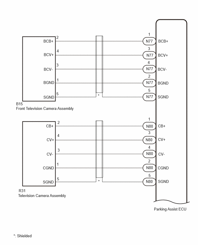
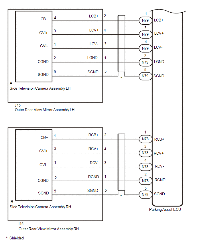
WIRING DIAGRAM
CAUTION / NOTICE / HINT
NOTICE:
Depending on the parts that are replaced or operations that are performed during vehicle inspection or maintenance, calibration of other systems as well as the panoramic view monitor system may be needed.
Click here
![2023 - 2025 MY RAV4 HV [10/2022 - ]; PARK ASSIST / MONITORING: PANORAMIC VIEW MONITOR SYSTEM (for HV Model): CALIBRATION](/t3Portal/stylegraphics/info.gif)
PROCEDURE
PROCEDURE
|
1. |
CHECK FOR DTCs |
(a) Turn the ignition switch to ON.
(b) Using the GTS, check for DTCs and proceed to the respective link below.
Chassis > Circumference Monitoring Camera Control Module > Trouble Codes
|
Result |
Proceed to |
|---|---|
|
Only DTC C162287 is output |
A |
|
Only DTC C168187 is output |
B |
|
Only DTC C168E87 is output |
C |
|
Only DTC C169D87 is output |
D |
|
Other than above |
E |
| B |

|
| C |
|
| D |
|
| E |
|
|

|
2. |
CHECK HARNESS AND CONNECTOR (PARKING ASSIST ECU - REAR TELEVISION CAMERA ASSEMBLY) |
Pre-procedure1
(a) Disconnect the N80 parking assist ECU connector.
(b) Disconnect the R31 rear television camera assembly connector.
Procedure1
(c) Measure the resistance according to the value(s) in the table below.
Standard Resistance:
|
Tester Connection |
Condition |
Specified Condition |
|---|---|---|
|
N80-1 (CB+) - R31-2 (CB+) |
Always |
Below 1 Ω |
|
N80-3 (CV+) - R31-4 (CV+) |
Always |
Below 1 Ω |
|
N80-4 (CV-) - R31-3 (CV-) |
Always |
Below 1 Ω |
|
N80-2 (CGND) - R31-1 (CGND) |
Always |
Below 1 Ω |
|
N80-5 (SGND) - R31-5 (SGND) |
Always |
Below 1 Ω |
|
N80-1 (CB+) or R31-2 (CB+) - Body ground |
Always |
10 kΩ or higher |
|
N80-3 (CV+) or R31-4 (CV+) - Body ground |
Always |
10 kΩ or higher |
|
N80-4 (CV-) or R31-3 (CV-) - Body ground |
Always |
10 kΩ or higher |
|
N80-2 (CGND) or R31-1 (CGND) - Body ground |
Always |
10 kΩ or higher |
|
N80-5 (SGND) or R31-5 (SGND) - Body ground |
Always |
10 kΩ or higher |
Post-procedure1
(d) None
| NG |
|
REPAIR OR REPLACE HARNESS OR CONNECTOR |
|
|
3. |
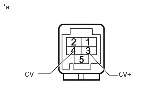
CHECK PARKING ASSIST ECU (CV+, CV-) |
Pre-procedure1
|
(a) Disconnect the N80 parking assist ECU connector. |
|
Procedure1
(b) Measure the resistance according to the value(s) in the table below.
Standard Resistance:
|
Tester Connection |
Condition |
Specified Condition |
|---|---|---|
|
3 (CV+) - Body ground |
Always |
10 kΩ or higher |
|
4 (CV-) - Body ground |
Always |
10 kΩ or higher |
Post-procedure1
(c) None
| NG |
|
|
|
4. |
CHECK PARKING ASSIST ECU (CB+, CGND) |
Pre-procedure1
(a) Disconnect the R31 rear television camera assembly.
Procedure1
(b) Measure the resistance according to the value(s) in the table below.
Standard Resistance:
|
Tester Connection |
Condition |
Specified Condition |
|---|---|---|
|
R31-1 (CGND) - Body ground |
Always |
Below 1 Ω |
(c) Measure the voltage according to the value(s) in the table below.
Standard Voltage:
|
Tester Connection |
Switch Condition |
Specified Condition |
|---|---|---|
|
R31-2 (CB+) - R31-1 (CGND) |
Ignition switch ON |
7.5 to 8.5 V |
|
R31-2 (CB+) - R31-1 (CGND) |
Ignition switch off |
Below 1 V |
Post-procedure1
(d) None
| OK |
|
| NG |
|
|
5. |
CHECK HARNESS AND CONNECTOR (PARKING ASSIST ECU - FRONT TELEVISION CAMERA ASSEMBLY) |
Pre-procedure1
(a) Disconnect the N77 parking assist ECU connector.
(b) Disconnect the B15 front television camera assembly connector.
Procedure1
(c) Measure the resistance according to the value(s) in the table below.
Standard Resistance:
|
Tester Connection |
Condition |
Specified Condition |
|---|---|---|
|
N77-1 (BCB+) - B15-2 (BCB+) |
Always |
Below 1 Ω |
|
N77-3 (BCV+) - B15-4 (BCV+) |
Always |
Below 1 Ω |
|
N77-4 (BCV-) - B15-3 (BCV-) |
Always |
Below 1 Ω |
|
N77-2 (BGND) - B15-1 (BGND) |
Always |
Below 1 Ω |
|
N77-5 (SGND) - B15-5 (SGND) |
Always |
Below 1 Ω |
|
N77-1 (BCB+) or B15-2 (BCB+) - Body ground |
Always |
10 kΩ or higher |
|
N77-3 (BCV+) or B15-4 (BCV+) - Body ground |
Always |
10 kΩ or higher |
|
N77-4 (BCV-) or B15-3 (BCV-) - Body ground |
Always |
10 kΩ or higher |
|
N77-2 (BGND) or B15-1 (BGND) - Body ground |
Always |
10 kΩ or higher |
|
N77-5 (SGND) or B15-5 (SGND) - Body ground |
Always |
10 kΩ or higher |
Post-procedure1
(d) None
| NG |
|
REPAIR OR REPLACE HARNESS OR CONNECTOR |
|
|
6. |
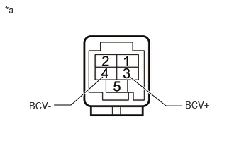
CHECK PARKING ASSIST ECU (BCV+, BCV-) |
Pre-procedure1
|
(a) Disconnect the N77 parking assist ECU connector. |
|
Procedure1
(b) Measure the resistance according to the value(s) in the table below.
Standard Resistance:
|
Tester Connection |
Condition |
Specified Condition |
|---|---|---|
|
3 (BCV+) - Body ground |
Always |
10 kΩ or higher |
|
4 (BCV-) - Body ground |
Always |
10 kΩ or higher |
Post-procedure1
(c) None
| NG |
|
|
|
7. |
CHECK PARKING ASSIST ECU (BCB+, BGND) |
Pre-procedure1
(a) Disconnect the B15 front television camera assembly connector.
Procedure1
(b) Measure the resistance according to the value(s) in the table below.
Standard Resistance:
|
Tester Connection |
Condition |
Specified Condition |
|---|---|---|
|
B15-1 (BGND) - Body ground |
Always |
Below 1 Ω |
(c) Measure the voltage according to the value(s) in the table below.
Standard Voltage:
|
Tester Connection |
Switch Condition |
Specified Condition |
|---|---|---|
|
B15-2 (BCB+) - B15-1 (BGND) |
Ignition switch ON |
7.5 to 8.5 V |
|
B15-2 (BCB+) - B15-1 (BGND) |
Ignition switch off |
Below 1 V |
Post-procedure1
(d) None
| OK |
|
| NG |
|
|
8. |
CHECK HARNESS AND CONNECTOR (PARKING ASSIST ECU - OUTER REAR VIEW MIRROR ASSEMBLY LH) |
Pre-procedure1
(a) Disconnect the N79 parking assist ECU connector.
(b) Disconnect the J15 outer rear view mirror assembly LH connector.
Procedure1
(c) Measure the resistance according to the value(s) in the table below.
Standard Resistance:
|
Tester Connection |
Condition |
Specified Condition |
|---|---|---|
|
N79-1 (LCB+) - J15-2 (LCB+) |
Always |
Below 1 Ω |
|
N79-3 (LCV+) - J15-4 (LCV+) |
Always |
Below 1 Ω |
|
N79-4 (LCV-) - J15-3 (LCV-) |
Always |
Below 1 Ω |
|
N79-2 (LGND) - J15-1 (LGND) |
Always |
Below 1 Ω |
|
N79-5 (SGND) - J15-5 (SGND) |
Always |
Below 1 Ω |
|
N79-1 (LCB+) or J15-2 (LCB+) - Body ground |
Always |
10 kΩ or higher |
|
N79-3 (LCV+) or J15-4 (LCV+) - Body ground |
Always |
10 kΩ or higher |
|
N79-4 (LCV-) or J15-3 (LCV-) - Body ground |
Always |
10 kΩ or higher |
|
N79-2 (LGND) or J15-1 (LGND) - Body ground |
Always |
10 kΩ or higher |
|
N79-5 (SGND) or J15-5 (SGND) - Body ground |
Always |
10 kΩ or higher |
Post-procedure1
(d) None
| NG |
|
REPAIR OR REPLACE HARNESS OR CONNECTOR |
|
|
9. |
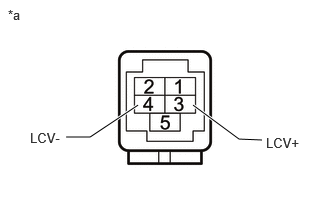
CHECK PARKING ASSIST ECU (LCV+, LCV-) |
Pre-procedure1
|
(a) Disconnect the N79 parking assist ECU connector. |
|
Procedure1
(b) Measure the resistance according to the value(s) in the table below.
Standard Resistance:
|
Tester Connection |
Condition |
Specified Condition |
|---|---|---|
|
3 (LCV+) - Body ground |
Always |
10 kΩ or higher |
|
4 (LCV-) - Body ground |
Always |
10 kΩ or higher |
Post-procedure1
(c) None
| NG |
|
|
|
10. |
CHECK PARKING ASSIST ECU (LCB+, LGND) |
Pre-procedure1
(a) Disconnect the J15 outer rear view mirror assembly LH connector.
Procedure1
(b) Measure the resistance according to the value(s) in the table below.
Standard Resistance:
|
Tester Connection |
Condition |
Specified Condition |
|---|---|---|
|
J15-1 (LGND) - Body ground |
Always |
Below 1 Ω |
(c) Measure the voltage according to the value(s) in the table below.
Standard Voltage:
|
Tester Connection |
Switch Condition |
Specified Condition |
|---|---|---|
|
J15-2 (LCB+) - J15-1 (LGND) |
Ignition switch ON |
7.5 to 8.5 V |
|
J15-2 (LCB+) - J15-1 (LGND) |
Ignition switch off |
Below 1 V |
(d) None
Post-procedure1
| NG |
|
|
|
11. |
INSPECT OUTER REAR VIEW MIRROR ASSEMBLY LH |
|
(a) Disconnect the outer rear view mirror assembly LH connector. |
|
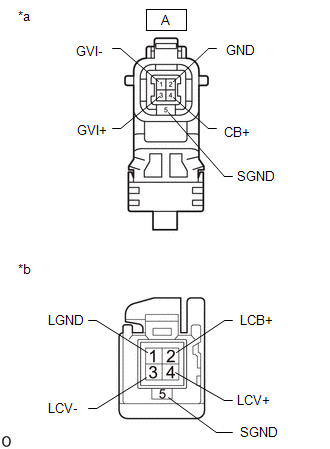
(b) Disconnect the side television camera assembly LH connector.
(c) Measure the resistance according to the value(s) in the table below.
Standard Resistance:
|
Tester Connection |
Condition |
Specified Condition |
|---|---|---|
|
2 (LCB+) - A-4 (CB+) |
Always |
Below 1 Ω |
|
4 (LCV+) - A-3 (GVI+) |
Always |
Below 1 Ω |
|
3 (LCV-) - A-1 (GVI-) |
Always |
Below 1 Ω |
|
1 (LGND) - A-2 (GND) |
Always |
Below 1 Ω |
|
5 (SGND) - A-5 (SGND) |
Always |
Below 1 Ω |
|
2 (LCB+) or A-4 (CB+) - Body ground |
Always |
10 kΩ or higher |
|
4 (LCV+) or A-3 (GVI+) - Body ground |
Always |
10 kΩ or higher |
|
3 (LCV-) or A-1 (GVI-) - Body ground |
Always |
10 kΩ or higher |
|
1 (LGND) or A-2 (GND) - Body ground |
Always |
10 kΩ or higher |
|
5 (SGND) or A-5 (SGND) - Body ground |
Always |
10 kΩ or higher |
| NG |
|
|
|
12. |
REPLACE SIDE TELEVISION CAMERA ASSEMBLY LH |
Click here
|
|
13. |
CLEAR DTC |
(a) Clear the DTCs.
Chassis > Circumference Monitoring Camera Control Module > Clear DTCs
|
|
14. |
CHECK FOR DTC |
(a) Check for DTCs.
Chassis > Circumference Monitoring Camera Control Module > Trouble Codes
|
Result |
Proceed to |
|---|---|
|
C168E87 is not output |
A |
|
C168E87 is output |
B |
| A |
|
END (SIDE TELEVISION CAMERA ASSEMBLY LH WAS DEFECTIVE) |
| B |
|
|
15. |
CHECK HARNESS AND CONNECTOR (PARKING ASSIST ECU - OUTER REAR VIEW MIRROR ASSEMBLY RH) |
Pre-procedure1
(a) Disconnect the N78 parking assist ECU connector.
(b) Disconnect the I15 outer rear view mirror assembly RH connector.
Procedure1
(c) Measure the resistance according to the value(s) in the table below.
Standard Resistance:
|
Tester Connection |
Condition |
Specified Condition |
|---|---|---|
|
N78-1 (RCB+) - I15-2 (RCB+) |
Always |
Below 1 Ω |
|
N78-3 (RCV+) - I15-4 (RCV+) |
Always |
Below 1 Ω |
|
N78-4 (RCV-) - I15-3 (RCV-) |
Always |
Below 1 Ω |
|
N78-2 (RGND) - I15-1 (RGND) |
Always |
Below 1 Ω |
|
N78-5 (SGND) - I15-5 (SGND) |
Always |
Below 1 Ω |
|
N78-1 (RCB+) or I15-2 (RCB+) - Body ground |
Always |
10 kΩ or higher |
|
N78-3 (RCV+) or I15-4 (RCV+) - Body ground |
Always |
10 kΩ or higher |
|
N78-4 (RCV-) or I15-3 (RCV-) - Body ground |
Always |
10 kΩ or higher |
|
N78-2 (RGND) or I15-1 (RGND) - Body ground |
Always |
10 kΩ or higher |
|
N78-5 (SGND) or I15-5 (SGND) - Body ground |
Always |
10 kΩ or higher |
Post-procedure1
(d) None
| NG |
|
REPAIR OR REPLACE HARNESS OR CONNECTOR |
|
|
16. |
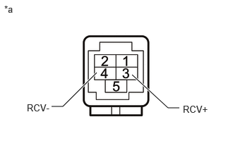
CHECK PARKING ASSIST ECU (RCV+, RCV-) |
Pre-procedure1
|
(a) Disconnect the N78 parking assist ECU connector. |
|
Procedure1
(b) Measure the resistance according to the value(s) in the table below.
Standard Resistance:
|
Tester Connection |
Condition |
Specified Condition |
|---|---|---|
|
3 (RCV+) - Body ground |
Always |
10 kΩ or higher |
|
4 (RCV-) - Body ground |
Always |
10 kΩ or higher |
Post-procedure1
(c) None
| NG |
|
|
|
17. |
CHECK PARKING ASSIST ECU (RCB+, RGND) |
Pre-procedure1
(a) Disconnect the I15 outer rear view mirror assembly RH connector.
Procedure1
(b) Measure the resistance according to the value(s) in the table below.
Standard Resistance:
|
Tester Connection |
Condition |
Specified Condition |
|---|---|---|
|
I15-1 (RGND) - Body ground |
Always |
Below 1 Ω |
(c) Measure the voltage according to the value(s) in the table below.
Standard Voltage:
|
Tester Connection |
Switch Condition |
Specified Condition |
|---|---|---|
|
I15-2 (RCB+) - I15-1 (RGND) |
Ignition switch ON |
7.5 to 8.5 V |
|
I15-2 (RCB+) - I15-1 (RGND) |
Ignition switch off |
Below 1 V |
Post-procedure1
(d) None
| NG |
|
|
|
18. |
INSPECT OUTER REAR VIEW MIRROR ASSEMBLY RH |
Pre-procedure1
|
(a) Disconnect the side television camera assembly RH connector. |
|
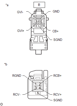
(b) Disconnect the outer rear view mirror assembly RH connector.
Procedure1
(c) Measure the resistance according to the value(s) in the table below.
Standard Resistance:
|
Tester Connection |
Condition |
Specified Condition |
|---|---|---|
|
2 (RCB+) - B-4 (CB+) |
Always |
Below 1 Ω |
|
4 (RCV+) - B-3 (GVI+) |
Always |
Below 1 Ω |
|
3 (RCV-) - B-1 (GVI-) |
Always |
Below 1 Ω |
|
1 (RGND) - B-2 (GND) |
Always |
Below 1 Ω |
|
5 (SGND) or B-5 (SGND) |
Always |
10 kΩ or higher |
|
2 (RCB+) or B-4 (RCB+) - Body ground |
Always |
10 kΩ or higher |
|
4 (RCV+) or B-3 (GVI+) - Body ground |
Always |
10 kΩ or higher |
|
3 (RCV-) or B-1 (GVI-) - Body ground |
Always |
10 kΩ or higher |
|
1 (RGND) or B-2 (GND) - Body ground |
Always |
10 kΩ or higher |
|
5 (SGND) or B-5 (SGND) - Body ground |
Always |
10 kΩ or higher |
(d) Post-procedure1
None
| NG |
|
|
|
19. |
REPLACE SIDE TELEVISION CAMERA ASSEMBLY RH |
Click here
|
|
20. |
CLEAR DTC |
(a) Clear the DTCs.
Chassis > Circumference Monitoring Camera Control Module > Clear DTCs
|
|
21. |
CHECK FOR DTC |
(a) Check for DTCs.
Chassis > Circumference Monitoring Camera Control Module > Trouble Codes
|
Result |
Proceed to |
|---|---|
|
C169D87 is not output |
A |
|
C169D87 is output |
B |
| A |
|
END (SIDE TELEVISION CAMERA ASSEMBLY RH WAS DEFECTIVE) |
| B |
|
|
22. |
CHECK FOR DTCs |
(a) Disconnect the N80 parking assist ECU connector.
(b) Using the GTS, check for DTCs and proceed to the respective link below.
Chassis > Circumference Monitoring Camera Control Module > Trouble Codes
|
Result |
Proceed to |
|---|---|
|
Only DTC C162287 is output |
A |
|
DTC C162287 is output together with either C168187, C168E87, or C169D87 |
B |
| A |
|
|
|
23. |
CHECK FOR DTCs |
(a) Connect the N80 parking assist ECU connector.
(b) Disconnect the N77 parking assist ECU connector.
(c) Using the GTS, check for DTCs and proceed to the respective link below.
Chassis > Circumference Monitoring Camera Control Module > Trouble Codes
|
Result |
Proceed to |
|---|---|
|
Only DTC C168187 is output |
A |
|
DTC C168187 is output together with either C162287, C168E87, or C169D87 |
B |
| A |
|
|
|
24. |
CHECK FOR DTCs |
(a) Connect the N77 parking assist ECU connector.
(b) Disconnect the N79 parking assist ECU connector.
(c) Using the GTS, check for DTCs and proceed to the respective link below.
Chassis > Circumference Monitoring Camera Control Module > Trouble Codes
|
Result |
Proceed to |
|---|---|
|
Only DTC C168E87 is output |
A |
|
DTC C168E87 is output together with either C162287, C168187, or C169D87 |
B |
| A |
|
|
|
25. |
CHECK FOR DTCs |
(a) Connect the N79 parking assist ECU connector.
(b) Disconnect the N78 parking assist ECU connector.
(c) Using the GTS, check for DTCs and proceed to the respective link below.
Chassis > Circumference Monitoring Camera Control Module > Trouble Codes
|
Result |
Proceed to |
|---|---|
|
Only DTC C169D87 is output |
A |
|
DTC C169D87 is output together with either C162287, C168187, or C168E87 |
B |
| A |
|
| B |
|
|
|
|