| 
                           Last Modified: 05-08-2025 | 
                        6.11:8.1.0  | 
                        
                           Doc ID: RM1000000027HAV | 
                      
                     
                        | 
                           Model Year Start: 2023 | 
                        
                           Model: RAV4 | 
                        
                           Prod Date Range: [10/2022 - 10/2023] | 
                      
                     
                        | 
                           Title: AXLE AND DIFFERENTIAL: REAR AXLE CARRIER (for AWD): REMOVAL; 2023 MY RAV4 RAV4 HV [10/2022 - 10/2023] | 
                      
                   
                  REMOVAL
                   
                  CAUTION / NOTICE / HINT
                  The necessary procedures (adjustment, calibration, initialization, or registration) that must be performed after parts are removed and installed, or replaced during rear axle carrier removal/installation are shown below. 
                  Necessary Procedures After Parts Removed/Installed/Replaced (for HV Model:)


                           | 
                               Replaced Part or Performed Procedure 
                            | 
                           
                               Necessary Procedure 
                            | 
                           
                               Effect/Inoperative Function When Necessary Procedures are not Performed 
                            | 
                           
                               Link 
                            | 


                           | 
                               Auxiliary battery terminal is disconnected/reconnected 
                            | 
                           
                               Perform steering sensor zero point calibration 
                            | 
                           
                               Lane control system 
                            | 


                            | 
                         
                        
                           | 
                               Parking support brake system (for HV model)* 
                            | 
                         
                        
                           | 
                               Pre-collision system 
                            | 
                         
                        
                           | 
                               Reset back door close position 
                            | 
                           
                               Power back door system (for HV model) 
                            | 


                            | 
                         
                        
                           | 
                               Back door lock initialization 
                            | 
                           
                               Power door lock control system 
                            | 


                            | 
                         
                        
                           | 
                               Rear wheel alignment adjustment 
                            | 


                                    - 
Perform "Reset Memory"
 
                                    - 
Perform "Calibration"


                            | 


                                    - 
DTCs are stored
 
                                    - 
ABS warning light illuminates
 
                                    - 
Brake system warning light (yellow indicator) illuminates
 
                                    - 
Slip indicator light illuminates
 
                                    - 
Brake control disabled or malfunctions (brake drag, etc.)


                            | 


                            | 
                         
                        
                           | 
                               Suspension, tires, etc. 
                            | 
                           
                               Television camera assembly optical axis (Back camera position setting) 
                            | 
                           
                               Parking assist monitor system 
                            | 


                            | 
                         
                        
                           | 
                               Parking assist ECU initialization 
                            | 
                           
                               Panoramic view monitor system (for HV model) 
                            | 


                            | 


                     NOTICE: 
                     
                        - 
After the ignition switch is turned off, the audio and visual system records various types of memory and settings. As a result, after turning the ignition switch off, make sure to wait at least 2 minutes before disconnecting the cable from the negative (-) auxiliary battery terminal.
 
                        - 
When the cable is disconnected from the negative (-) auxiliary battery terminal and the security lock setting has been enabled, multi-display operations will be disabled upon next startup unless the password is entered. Be sure to check the security lock setting before disconnecting the cable from the negative (-) auxiliary battery terminal.


                  Necessary Procedures After Parts Removed/Installed/Replaced (for Gasoline Model:)


                           | 
                               Replaced Part or Performed Procedure 
                            | 
                           
                               Necessary Procedure 
                            | 
                           
                               Effect/Inoperative Function When Necessary Procedures are not Performed 
                            | 
                           
                               Link 
                            | 


                           | 
                               Rear wheel alignment adjustment 
                            | 


                                    - 
Perform "Reset Memory".
 
                                    - 
Perform acceleration sensor zero point calibration and store system information memorization.


                            | 


                                    - 
VSC is disabled or malfunctions
 
                                    - 
DTCs are output
 
                                    - 
Slip indicator light illuminates
 
                                    - 
ABS warning light illuminates


                            | 


                            | 
                         
                        
                           | 
                               Suspension, tires, etc. 
                            | 
                           
                               Television camera assembly optical axis (Back camera position setting) 
                            | 
                           
                               Parking assist monitor system 
                            | 


                            | 
                         
                        
                           | 
                               Parking assist ECU initialization 
                            | 
                           
                               Panoramic view monitor system (for Gasoline model) 
                            | 


                            | 


                     HINT: 
                     
                        - 
Use the same procedure for the RH and LH sides.
 
                        - 
The following procedure is for the LH side.


                  PROCEDURE
                   
                  1. RELEASE PARKING BRAKE 
                  Click here


                  2. DISABLE BRAKE CONTROL (w/o Vacuum Brake Booster) 
                  Click here


                  3. REMOVE REAR WHEEL 
                  Click here


                  4. REMOVE LOWER NO. 2 CONTROL ARM COVER (w/ Cover) 
                  Click here


                  5. DISCONNECT NO. 2 PARKING BRAKE WIRE ASSEMBLY 


                           | 
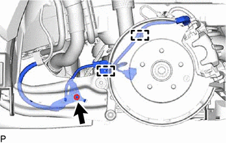
                               (a) Disconnect the No. 2 parking brake wire assembly connector from the parking brake actuator assembly. 
                              
                                 NOTICE: 
                                 
                                    - 
Remove any dirt or foreign matter on and around the No. 2 parking brake wire assembly connector before performing this step.
 
                                    - 
Do not allow water, oil or dirt to enter the No. 2 parking brake wire assembly connector.


                            | 
                           
                              
                            | 


                           | 
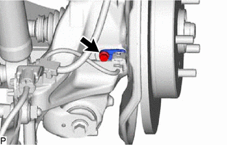
                               (b) Remove the bolt and disconnect the skid control sensor from the rear axle carrier sub-assembly. 
                              
                                 NOTICE: 
                                 
                                    - 
Keep the tip of the skid control sensor and installation hole free of foreign matter.
 
                                    - 
Do not rotate or apply excessive force to the skid control sensor when removing it from the rear axle carrier sub-assembly. Rotating or applying excessive force may result in damage to the skid control sensor.


                            | 
                           
                              
                            | 


                           | 
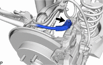
                               (c) Remove the nut, disengage the 2 clamps and separate the No. 2 parking brake wire assembly from the rear flexible hose bracket and rear trailing arm assembly. 
                            | 
                           
                              
                            | 


                  6. DISCONNECT REAR FLEXIBLE HOSE 


                           | 
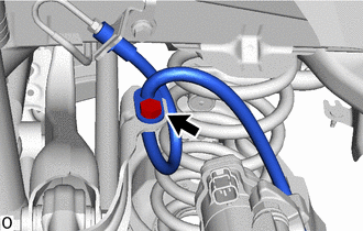
                               (a) Remove the bolt and disconnect the rear flexible hose from the rear flexible hose bracket. 
                            | 
                           
                              
                            | 


                  7. REMOVE REAR AXLE SHAFT NUT 
                  Click here


                  8. DISCONNECT REAR DISC BRAKE CALIPER ASSEMBLY LH 


                           | 
                               (a) Remove the 2 bolts and disconnect the rear disc brake caliper assembly from the rear axle carrier sub-assembly. 
                              NOTICE: 
                              Use wire or an equivalent tool to keep the rear disc brake caliper assembly from hanging by the rear flexible hose. 
                            | 
                           
                              
                            | 


                  9. REMOVE REAR DISC 
                  Click here


                  10. REMOVE REAR AXLE HUB AND BEARING ASSEMBLY LH 
                  Click here


                  11. REMOVE NO. 2 FLEXIBLE HOSE BRACKET 


                           | 
                               (a) Remove the bolt and flexible hose bracket from the rear axle carrier sub-assembly. 
                            | 
                           
                              
                            | 


                  12. REMOVE REAR STABILIZER LINK ASSEMBLY LH 
                  Click here


                  13. REMOVE REAR COIL SPRING LH 
                  Click here


                  14. REMOVE REAR LOWER COIL SPRING INSULATOR LH 
                  Click here


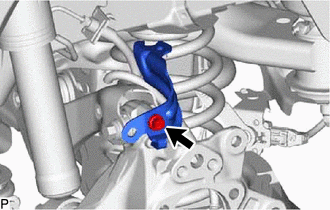
                  15. REMOVE REAR NO. 1 SUSPENSION ARM ASSEMBLY LH 


                           | 
                               (a) Remove the bolt, nut and rear No. 1 suspension arm assembly LH from the rear axle carrier sub-assembly and rear suspension member sub-assembly. 
                              NOTICE: 
                              Because the nut has its own stopper, do not turn the nut. Loosen the bolt with the nut secured. 
                            | 
                           
                              
                            | 


                  16. REMOVE REAR AXLE CARRIER SUB-ASSEMBLY 


                           | 
                               (a) Loosen the 3 bolts and nut of the rear trailing arm assembly. 
                            | 
                           
                              
                            | 


                           | 
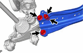
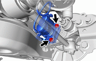
                               (b) Loosen the nut of the rear shock absorber assembly. 
                              NOTICE: 
                              Hold the rear axle carrier pin while rotating the nut. 
                            | 
                           
                              
                            | 


                           | 
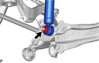
                               (c) Using a jack and wooden block, support the rear axle carrier sub-assembly. 
                              
                                 NOTICE: 
                                 
                                    - 
When jacking up the rear axle carrier sub-assembly, be sure to jack it up slowly.
 
                                    - 
Make sure to perform this operation with the vehicle kept as low as possible.


                            | 
                           
                              
                            | 


                           | 
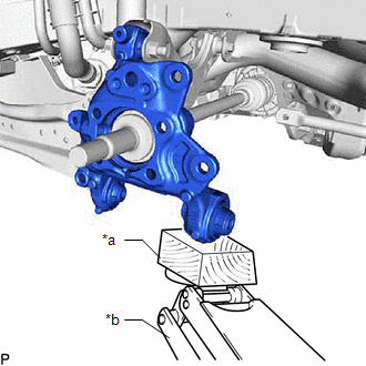
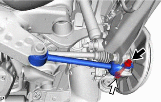
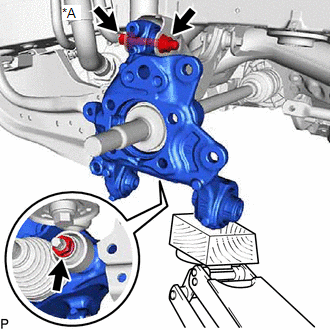
                               (d) Loosen the bolt (A). 
                              NOTICE: 
                              Because the nut has its own stopper, do not turn the nut. Loosen the bolt with the nut secured. 
                            | 
                           
                              
                            | 


                  (e) Remove the 3 bolts, nut and disconnect the rear trailing arm assembly from the rear axle carrier sub-assembly. 
                  (f) Remove the nut and disconnect the rear shock absorber assembly from the rear axle carrier sub-assembly. 
                  NOTICE: 
                  Hold the rear axle carrier pin while rotating the nut. 
                  (g) Remove the bolt (A), nut and rear axle carrier sub-assembly from the rear upper control arm assembly. 
                  NOTICE: 
                  Because the nut has its own stopper, do not turn the nut. Loosen the bolt with the nut secured. 
                  
                |