- Replacement of throttle body with motor assembly
- Replacement of EGR valve assembly
- Gas leaks from exhaust system
| Last Modified: 01-30-2024 | 6.11:8.1.0 | Doc ID: RM100000002FRAP |
| Model Year Start: 2024 | Model: RAV4 | Prod Date Range: [10/2023 - ] |
| Title: A25A-FKS (COOLING): THERMOSTAT: REMOVAL; 2024 MY RAV4 [10/2023 - ] | ||
REMOVAL
CAUTION / NOTICE / HINT
The necessary procedures (adjustment, calibration, initialization, or registration) that must be performed after parts are removed and installed, or replaced during water inlet with thermostat sub-assembly removal/installation are shown below.
Necessary Procedures After Parts Removed/Installed/Replaced
|
Replaced Part or Performed Procedure |
Necessary Procedure |
Effect/Inoperative Function when Necessary Procedure not Performed |
Link |
|---|---|---|---|
|
*1: When performing learning using the Techstream.
*2: w/o Power Back Door System |
|||
|
Battery terminal is disconnected/reconnected |
Drive the vehicle until stop and start control is permitted (approximately 5 to 60 minutes) |
Stop and start system |
|
|
Perform steering sensor zero point calibration |
Lane control system |
||
|
Parking support brake system (for Gasoline model)*1 |
|||
|
Pre-collision system |
|||
|
Reset back door close position |
Power back door system |
||
|
Back door lock initialization*2 |
Power door lock control system |
||
|
|
Inspection after repair |
|
|
NOTICE:
- After the ignition switch is turned off, the audio and visual system records various types of memory and settings. As a result, after turning the ignition switch off, make sure to wait at least 2 minutes before disconnecting the cable from the negative (-) auxiliary battery terminal.
- When the cable is disconnected from the negative (-) auxiliary battery terminal and the security lock setting has been enabled, multi-display operations will be disabled upon next startup unless the password is entered. Be sure to check the security lock setting before disconnecting the cable from the negative (-) auxiliary battery terminal.
- This procedure includes the removal of small-head bolts. Refer to Small-Head Bolts of Basic Repair Hint to identify the small-head bolts.
PROCEDURE
1. DRAIN ENGINE COOLANT
2. REMOVE INTAKE MANIFOLD
3. REMOVE GENERATOR ASSEMBLY
4. DISCONNECT NO. 2 RADIATOR HOSE
|
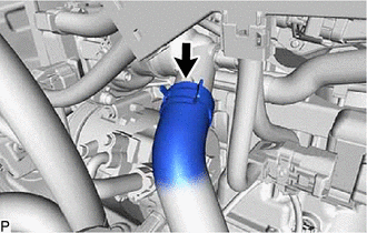
(a) Slide the clip and disconnect the No. 2 radiator hose from the water inlet with thermostat sub-assembly. |
|
5. REMOVE WATER INLET WITH THERMOSTAT SUB-ASSEMBLY
|
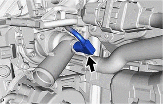
(a) Disconnect the water inlet with thermostat sub-assembly connector. |
|
|
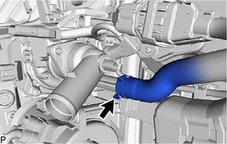
(b) Slide the clip and disconnect the No. 7 water by-pass hose from the water inlet with thermostat sub-assembly. NOTICE:
HINT: When disconnecting the No. 7 water by-pass hose, slide the clip, rotate the hose and pull it straight off the pipe. |
|
|
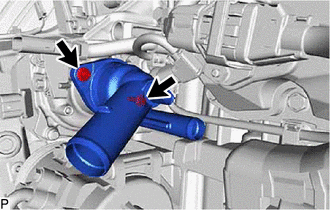
(c) Using an 8 mm socket wrench, remove the 2 bolts and water inlet with thermostat sub-assembly. |
|
|
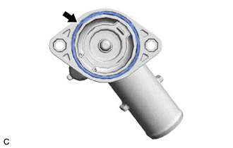
(d) Remove the gasket from the water inlet with thermostat sub-assembly. |
|
|
|
|
![2024 MY RAV4 [10/2023 - ]; PARK ASSIST / MONITORING: PARKING SUPPORT BRAKE SYSTEM (for Gasoline Model): CALIBRATION](/t3Portal/stylegraphics/info.gif)
