- Auto operation function
- Jam protection function
- Key-off operation function
- Key-linked function
- Wireless transmitter-linked function
- Sliding roof open warning function
- Sliding roof may move in reverse or become misaligned
| Last Modified: 01-30-2024 | 6.11:8.1.0 | Doc ID: RM100000002GM5G |
| Model Year Start: 2024 | Model: RAV4 | Prod Date Range: [10/2023 - ] |
| Title: SLIDING ROOF / CONVERTIBLE: SLIDING ROOF HOUSING (for Moon Roof): REMOVAL; 2024 MY RAV4 RAV4 HV [10/2023 - ] | ||
REMOVAL
CAUTION / NOTICE / HINT
The necessary procedures (adjustment, calibration, initialization or registration) that must be performed after parts are removed and installed, or replaced during sliding roof housing sub-assembly removal/installation are shown below.
Necessary Procedure after parts Removed/Installed/Replaced (for HV Model)
|
Replaced Part or Performed Procedures |
Necessary Procedures |
Effect/Inoperative Function when Necessary Procedures are not Performed |
Link |
|---|---|---|---|
| *: When performing learning using the Techstream. | |||
|
Removal and installation of auxiliary battery terminal |
Perform steering sensor zero point calibration |
Lane control system |
|
|
Parking support brake system (for HV model)* |
|||
|
Pre-collision system |
|||
|
Reset back door close position |
Power back door system |
||
|
Back door lock initialization |
Power door lock control system |
||
|
Sliding roof ECU (sliding roof drive gear sub-assembly) |
Initialize sliding roof system |
|
|
|
Sliding roof drive cable sub-assembly (Including removal and installation) |
Initialize sliding roof system |
|
|
|
Sliding roof glass sub-assembly (Including removal and installation) |
Initialize sliding roof system |
|
|
NOTICE:
- After the ignition switch is turned off, the audio and visual system records various types of memory and settings. As a result, after turning the ignition switch off, make sure to wait at least 2 minutes before disconnecting the cable from the negative (-) auxiliary battery terminal.
- When the cable is disconnected from the negative (-) auxiliary battery terminal and the security lock setting has been enabled, multi-display operations will be disabled upon next startup unless the password is entered. Be sure to check the security lock setting before disconnecting the cable from the negative (-) auxiliary battery terminal.
Necessary Procedure After Parts Removed/Installed/Replaced (for Gasoline Model)
|
Replaced Part or Performed Procedures |
Necessary Procedures |
Effect/Inoperative Function when Necessary Procedures are not Performed |
Link |
|---|---|---|---|
|
*1: When performing learning using the Techstream.
*2: w/o Power Back Door System |
|||
|
Removal and installation of auxiliary battery terminal |
Drive the vehicle until stop and start control is permitted (approximately 5 to 60 minutes) |
Stop and start system |
|
|
Perform steering sensor zero point calibration |
Lane control system |
||
|
Parking support brake system (for Gasoline model)*1 |
|||
|
Pre-collision system |
|||
|
Reset back door close position |
Power back door system |
||
|
Back door lock initialization*2 |
Power door lock control system |
||
|
Sliding roof ECU (Sliding roof drive gear sub-assembly) |
Initialize sliding roof system |
|
|
|
Sliding roof drive cable sub-assembly (Including removal and installation) |
Initialize sliding roof system |
|
|
|
Sliding roof glass sub-assembly (Including removal and installation) |
Initialize sliding roof system |
|
|
NOTICE:
- After the ignition switch is turned off, the audio and visual system records various types of memory and settings. As a result, after turning the ignition switch off, make sure to wait at least 2 minutes before disconnecting the cable from the negative (-) auxiliary battery terminal.
- When the cable is disconnected from the negative (-) auxiliary battery terminal and the security lock setting has been enabled, multi-display operations will be disabled upon next startup unless the password is entered. Be sure to check the security lock setting before disconnecting the cable from the negative (-) auxiliary battery terminal.
PROCEDURE
1. PRECAUTION
CAUTION:
Be sure to read precaution thoroughly before servicing.
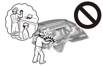
NOTICE:
After turning the ignition switch off, waiting time may be required before disconnecting the cable from the negative (-) auxiliary battery terminal. Therefore, make sure to read the disconnecting the cable from the negative (-) auxiliary battery terminal notices before proceeding with work.
2. REMOVE SLIDING ROOF SIDE GARNISH LH
|
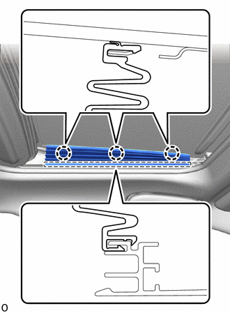
(a) Detach the claw and remove the sliding roof side garnish LH. |
|
3. REMOVE SLIDING ROOF SIDE GARNISH RH
HINT:
Use the same procedure described for the LH side.
4. REMOVE SLIDING ROOF GLASS SUB-ASSEMBLY
|
(a) Move the sliding roof glass sub-assembly to the fully closed position. |
|
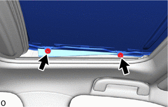
(b) Using a T25 "TORX" socket wrench, remove the 4 "TORX" screws and sliding roof glass sub-assembly.
HINT:
Use the same procedure for the RH side and LH side.
NOTICE:
To prevent the sliding roof glass sub-assembly and sliding roof drive gear assembly from becoming misaligned, move the sliding roof glass sub-assembly to the fully closed position before removing it.
5. DISCONNECT CABLE FROM NEGATIVE AUXILIARY BATTERY TERMINAL
(a) for A25A-FXS:
(b) for A25A-FKS:
CAUTION:
- Wait at least 90 seconds after disconnecting the cable from the negative (-) auxiliary battery terminal to disable the SRS system.
- If the airbag deploys for any reason, it may cause a serious accident.
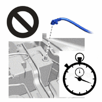
NOTICE:
When disconnecting the cable, some systems need to be initialized after the cable is reconnected.
6. REMOVE CURTAIN SHIELD AIRBAG ASSEMBLY LH
7. REMOVE CURTAIN SHIELD AIRBAG ASSEMBLY RH
HINT:
Use the same procedure described for the LH side.
8. DISCONNECT SLIDING ROOF DRAIN HOSE
(a) Detach the sliding roof drain hose clamp and disconnect the 4 sliding roof drain hoses.
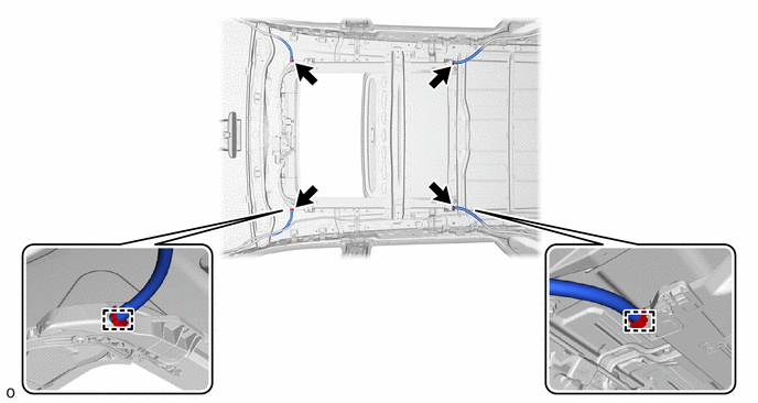
HINT:
Use the same procedure for all of the sliding roof drain hoses.
9. REMOVE SLIDING ROOF HOUSING SUB-ASSEMBLY
(a) Remove the 4 bolts, 6 nuts and sliding roof housing sub-assembly.
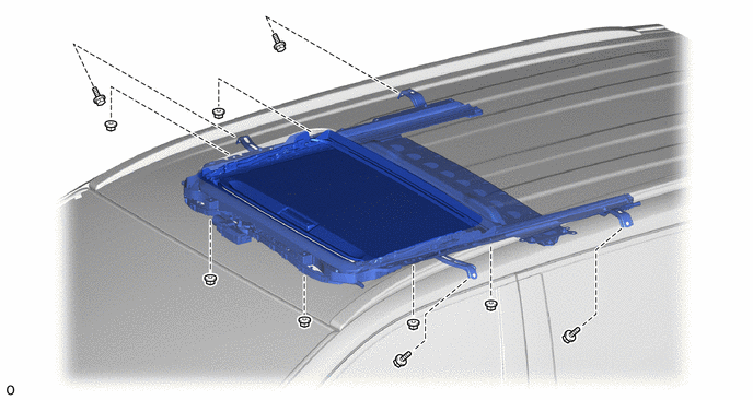
NOTICE:
If the removed nut is the same shape as that shown in the illustration, replace it the supplied replacement part.
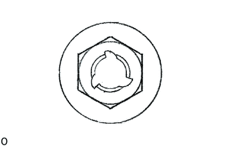
|
|
|
![2024 MY RAV4 HV [10/2023 - ]; PARK ASSIST / MONITORING: PARKING SUPPORT BRAKE SYSTEM (for HV Model): CALIBRATION](/t3Portal/stylegraphics/info.gif)
