| 
                           Last Modified: 05-08-2025 | 
                        6.11:8.1.0  | 
                        
                           Doc ID: RM100000002P1J5 | 
                      
                     
                        | 
                           Model Year Start: 2024 | 
                        
                           Model: RAV4 HV | 
                        
                           Prod Date Range: [10/2023 -                    
                                       ] | 
                      
                     
                        | 
                           Title: REAR SUSPENSION: REAR SUSPENSION MEMBER (for HV Model AWD): INSTALLATION; 2024 - 2025 MY RAV4 HV [10/2023 -        ] | 
                      
                   
                  INSTALLATION
                   
                  PROCEDURE
                   
                  1. INSTALL HOLE PLUG 


                           | 
                               (a) Install the 6 hole plugs to the rear suspension member sub-assembly. 
                              HINT: 
                              There are 2 different shapes of hole plug. 
                            | 
                           
                              
                            | 


                  2. INSTALL DIFFERENTIAL MOUNT CUSHION 
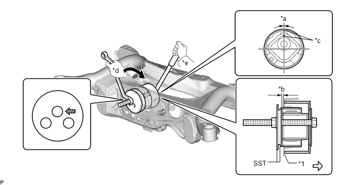
                  (a) Using SST, install a new differential mount cushion. 
                  SST: 09316-12010 
                  SST: 09570-24011 


                           | 
                               *1 
                            | 
                           
                               Rear Suspension Member Sub-assembly 
                            | 
                           
                               - 
                            | 
                           
                               - 
                            | 
                         
                        
                           | 
                               *a 
                            | 
                           
                               -3° to 3° 
                            | 
                           
                               *b 
                            | 
                           
                               3.1 to 4.1 mm (0.1220 to 0.1614 in.) 
                            | 
                         
                        
                           | 
                               *c 
                            | 
                           
                               Protrusion 
                            | 
                           
                               *d 
                            | 
                           
                               Turn 
                            | 
                         
                        
                           | 
                               *e 
                            | 
                           
                               Hold 
                            | 
                           
                               - 
                            | 
                           
                               - 
                            | 


                            | 
                           
                               Turning Direction 
                            | 
                           
                               
                            | 
                           
                               Front of Vehicle 
                            | 


                            | 
                           
                               SST Bolt Position 
                            | 
                           
                               - 
                            | 
                           
                               - 
                            | 


                     NOTICE: 
                     
                        - 
Make sure that the differential mount cushion is aligned within 3° from the center.
 
                        - 
Install the differential mount cushion so that the protrusion is positioned as shown in the illustration.
 
                        - 
Be sure to use the correct combination of SST.
 
                        - 
Before using SST, apply grease to SST bolt.
 
                        - 
Temporarily install the differential mount cushion to the rear suspension member sub-assembly in order to prevent it from tilting, and then install SST.
 
                        - 
Make sure that SST contacts the entire circumference of the differential mount cushion.
 
                        - 
Do not tilt the bolts of SST.


                  3. INSTALL REAR SUSPENSION MEMBER FRONT BODY MOUNTING CUSHION (for LH Side) 
                  Click here


                  4. INSTALL REAR SUSPENSION MEMBER FRONT BODY MOUNTING CUSHION (for RH Side) 
                  Click here


                  5. INSTALL REAR SUSPENSION MEMBER REAR BODY MOUNT CUSHION LH 
                  Click here


                  6. INSTALL REAR SUSPENSION MEMBER REAR BODY MOUNT CUSHION RH 
                  Click here


                  7. INSTALL REAR UPPER CONTROL ARM ASSEMBLY LH 
                  Click here


                  8. INSTALL REAR UPPER CONTROL ARM ASSEMBLY RH 
                  HINT: 
                  Perform the same procedure as for the LH side. 
                   
                  9. INSTALL REAR TRACTION MOTOR WITH TRANSAXLE ASSEMBLY 
                  Click here


                  10. CONNECT WIRE HARNESS 
                  Click here


                  11. INSTALL REAR SUSPENSION MEMBER SUB-ASSEMBLY 
                  (a) for TMC Made: 
                  (1) Install the 4 rear suspension member cushions to the rear suspension member sub-assembly. 
                  HINT: 
                  When reusing the rear suspension member cushion, make sure to check its identification mark and install it to the correct position. 
                  (b) for TMMC Made: 
                  (1) Install the 2 rear suspension member cushions and 2 upper differential support member stoppers to the rear suspension member sub-assembly. 
                  HINT: 
                  When reusing the rear suspension member cushion and upper differential support member stopper, make sure to check its identification mark and install it to the correct position. 
                  (c) Using an engine lifter and 4 attachments or equivalent tools, support the rear suspension member sub-assembly as shown in the illustration. 
                  
                     CAUTION: 
                     
                        - 
The rear suspension member sub-assembly is a very heavy component. Make sure that it is supported securely.
 
                        - 
If the rear suspension member sub-assembly is not securely supported, it may drop, resulting in serious injury.
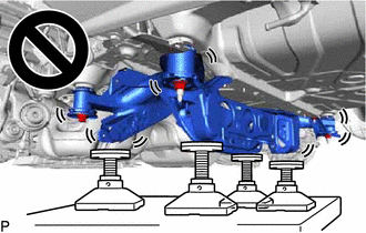


                     NOTICE: 
                     
                        - 
Use attachments or equivalent tools to keep the rear suspension member sub-assembly level.
 
                        - 
Keep supporting the rear suspension member sub-assembly until the installation has been completed.


                           | 
                               *a 
                            | 
                           
                               Engine Lifter 
                            | 
                         
                        
                           | 
                               *b 
                            | 
                           
                               Attachment 
                            | 


                            | 
                           
                               Attachment and Wooden Block Placement Location 
                            | 


                  (d) Raise the rear suspension member sub-assembly until there is no clearance between the rear suspension member sub-assembly and vehicle. 
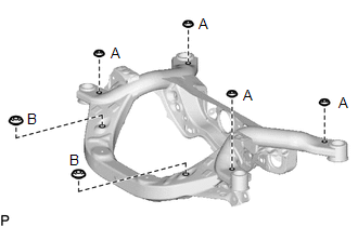
                  (e) Install the rear suspension member sub-assembly with the 2 rear suspension member lower stoppers, rear suspension member lower brace LH and rear suspension member lower brace RH, 2 bolts and 4 nuts. 
                  Torque:  
                  Bolt A :   
                  158 N·m {1611 kgf·cm, 117 ft·lbf} 
                  Nut B :   
                  158 N·m {1611 kgf·cm, 117 ft·lbf} 
                  Nut C :   
                  18 N·m {184 kgf·cm, 13 ft·lbf} 
                  (f) w/ Height Control Sensor: 
                  (1) Engage the 5 clamps to install the wire harness. 
                  (g) w/o Height Control Sensor: 
                  (1) Engage the 4 clamps to install the wire harness. 
                  (h) Pass the connector through the hole to the inside of the vehicle and install the grommet of the wire harness. 
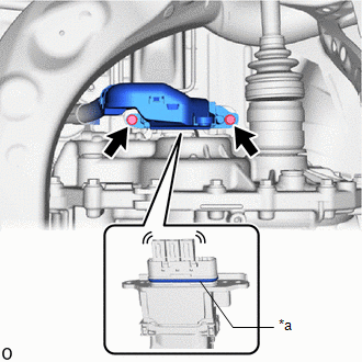
                  (i) w/ Height Control Sensor: 
                  (1) Connect the 2 connectors. 
                  (j) w/o Height Control Sensor: 
                  (1) Connect the connector. 
                   
                  12. INSTALL FLOOR UNDER WIRE 
                  CAUTION: 
                  Be sure to wear insulated gloves. 


                           | 
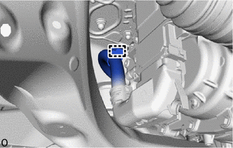
                               (a) Install the HV floor under wire to the rear traction motor with transaxle assembly with the 2 bolts. 
                              Torque:  
                              8.0 N·m {82 kgf·cm, 71 in·lbf} 
                              
                                 NOTICE: 
                                 
                                    - 
Make sure that the connector is fully engaged.
 
                                    - 
Do not damage the terminals, interlock connector or rear traction motor with transaxle assembly during installation.
 
                                    - 
Do not touch the waterproof seal or terminals of the connector.
 
                                    - 
Do not allow any foreign matter or water to enter the rear traction motor with transaxle assembly.
 
                                    - 
Although the connector may feel loose, this is not due to a malfunction.


                            | 
                           
                              
                            | 


                  13. TEMPORARILY INSTALL REAR NO. 1 SUSPENSION ARM ASSEMBLY LH 
                  (a) Temporarily install the rear No. 1 suspension arm assembly to the rear suspension member sub-assembly with the  bolt and  nut. 
                  
                     NOTICE: 
                     
                        - 
Because the nut has its own stopper, do not turn the nut. Tighten the bolt with the nut secured.
 
                        - 
Insert the bolt with the threaded end facing the rear of the vehicle.


                  14. TEMPORARILY INSTALL REAR NO. 1 SUSPENSION ARM ASSEMBLY RH 
                  HINT: 
                  Perform the same procedure as for the LH side. 
                   
                  15. TEMPORARILY INSTALL REAR NO. 2 SUSPENSION ARM ASSEMBLY LH 
                  Click here


                  16. TEMPORARILY INSTALL REAR NO. 2 SUSPENSION ARM ASSEMBLY RH 
                  HINT: 
                  Perform the same procedure as for the LH side. 
                   
                  17. INSTALL REAR DRIVE SHAFT ASSEMBLY LH 
                  Click here


                  18. INSTALL REAR DRIVE SHAFT ASSEMBLY RH 
                  HINT: 
                  Perform the same procedure as for the LH side. 
                   
                  19. INSTALL REAR STABILIZER BAR 
                  Click here


                  20. INSTALL DECK TRIM SIDE PANEL ASSEMBLY LH 
                  Click here


                  21. INSTALL LUGGAGE HOLD BELT STRIKER ASSEMBLY 
                  Click here


                  22. INSTALL TETHER ANCHOR BRACKET SET 
                  Click here


                  23. INSTALL REAR SEAT SIDE GARNISH LH 
                  Click here


                  24. INSTALL REAR DOOR OPENING TRIM WEATHERSTRIP LH 
                  Click here


                  25. INSTALL REAR DOOR SCUFF PLATE LH 
                  Click here


                  26. INSTALL REAR NO. 1 FLOOR MAT SUPPORT SIDE PLATE 
                  Click here


                  27. INSTALL REAR FLOOR FINISH PLATE 
                  Click here


                  28. INSTALL REAR NO. 3 FLOOR BOARD 
                  Click here


                  29. INSTALL REAR DECK FLOOR BOX (w/o Spare Tire) 
                  Click here


                  30. INSTALL DECK BOARD ASSEMBLY 
                  Click here


                  31. INSTALL TONNEAU COVER ASSEMBLY (w/ Tonneau Cover) 
                  Click here


                  32. INSTALL CHILD RESTRAINT SEAT ANCHOR BRACKET SUB-ASSEMBLY LH 
                  Click here


                  33. INSTALL REAR SEAT ASSEMBLY 
                  Click here


                  34. STABILIZE SUSPENSION 
                  Click here


                  35. INSTALL REAR NO. 1 SUSPENSION ARM ASSEMBLY LH 
                  Click here


                  36. INSTALL REAR NO. 1 SUSPENSION ARM ASSEMBLY RH 
                  HINT: 
                  Perform the same procedure as for the LH side. 
                   
                  37. INSTALL NO. 1 FLOOR UNDER COVER (w/ NO. 1 FLOOR UNDER COVER) 
                  (a) Install the No. 1 floor under cover to the rear suspension member sub-assembly with the 3 bolts and 3 clips. 
                  Torque:  
                  Bolt :   
                  7.5 N·m {76 kgf·cm, 66 in·lbf} 
                   
                  38. INSTALL SERVICE PLUG GRIP 
                  Click here


                  39. INSTALL REAR WHEEL 
                  Click here


                  40. INSPECT AND ADJUST REAR WHEEL ALIGNMENT 
                  Click here


                  41. PERFORM INITIALIZATION 
                  Click here


                |