
- Power switch off
- Electrical key transmitter sub-assembly brought outside vehicle
- All doors locked
- Electrical key transmitter sub-assembly not near the vehicle
- Rear door LH unlock sensor touched
| Last Modified: 05-08-2025 | 6.11:8.1.0 | Doc ID: RM100000002PC5L |
| Model Year Start: 2024 | Model: RAV4 HV | Prod Date Range: [10/2023 - 11/2024] |
| Title: THEFT DETERRENT / KEYLESS ENTRY: SMART KEY SYSTEM (for Entry Function, HV Model): Rear Door LH Entry Unlock Function does not Operate; 2024 MY RAV4 HV [10/2023 - 11/2024] | ||
|
Rear Door LH Entry Unlock Function does not Operate |
DESCRIPTION
If the entry unlock function does not operate for the rear door LH only, but the entry lock function operates, the request code is being transmitted properly from the rear door LH. In this case, there may be a problem related to the unlock sensor (connection between the certification ECU (smart key ECU assembly) and rear door outside handle assembly LH).
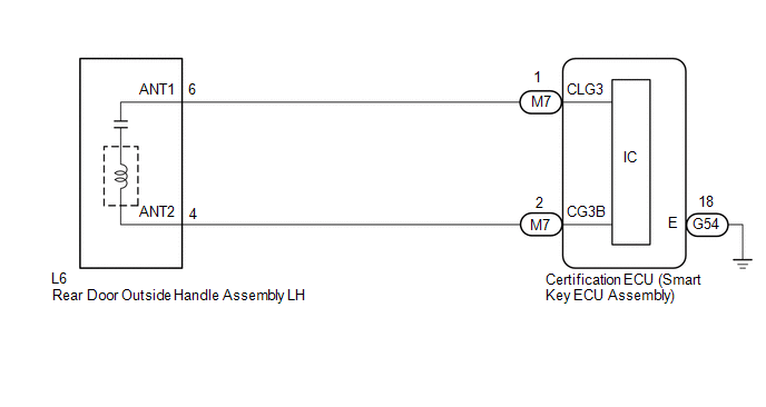
WIRING DIAGRAM
CAUTION / NOTICE / HINT
NOTICE:
- When using the Techstream with the power switch off, connect the Techstream to the DLC3 and turn a courtesy light switch on and off at intervals of 1.5 seconds or less until communication between the Techstream and the vehicle begins. Then select the vehicle type under manual mode and enter the following menus: Body Electrical / Smart Key. While using the Techstream, periodically turn a courtesy light switch on and off at intervals of 1.5 seconds or less to maintain communication between the Techstream and the vehicle.
-
The smart key system (for Entry Function) uses the LIN communication system and CAN communication system. Inspect the communication function by following How to Proceed with Troubleshooting. Troubleshoot the smart key system (for Entry Function) after confirming that the communication systems are functioning properly.
Click here
![2024 - 2025 MY RAV4 HV [10/2023 - ]; THEFT DETERRENT / KEYLESS ENTRY: SMART KEY SYSTEM (for Start Function, HV Model): HOW TO PROCEED WITH TROUBLESHOOTING](/t3Portal/stylegraphics/info.gif)
-
Before replacing the certification ECU (smart key ECU assembly), refer to Registration.
Click here
- After repair, confirm that no DTCs are output.
- Check that there are no electrical key transmitter sub-assemblies in the vehicle.
PROCEDURE
|
1. |
CHECK POWER DOOR LOCK CONTROL SYSTEM |
(a) When the door control switch on the multiplex network master switch assembly is operated, check that the doors unlock and lock according to the switch operation.
Click here
OK:
Door locks operate normally.
| NG |

|
|
|
2. |
READ VALUE USING TECHSTREAM (RL-DOOR LOCK POS SW, RL DOOR LOCK POSITION SWITCH STATUS) |
(a) Connect the Techstream to the DLC3.
(b) Turn the power switch on (IG).
(c) Turn the Techstream on.
(d) Enter the following menus: Body Electrical / Main Body / Data List.
(e) Read the Data List according to the display on the Techstream.
for Type A:
Body Electrical > Main Body > Data List
|
Tester Display |
Measurement Item |
Range |
Normal Condition |
Diagnostic Note |
|---|---|---|---|---|
|
RL Door Lock Position Switch Status |
Rear door LH unlock detection switch signal |
Lock or Unlock |
Lock: Rear door LH locked Unlock: Rear door LH unlocked |
- |
Body Electrical > Main Body > Data List
|
Tester Display |
|---|
|
RL Door Lock Position Switch Status |
for Type B:
Body Electrical > Main Body > Data List
|
Tester Display |
Measurement Item |
Range |
Normal Condition |
Diagnostic Note |
|---|---|---|---|---|
|
RL-Door Lock Pos SW |
Rear door LH unlock detection switch signal |
ON or OFF |
ON: Rear door LH unlocked OFF: Rear door LH locked |
- |
Body Electrical > Main Body > Data List
|
Tester Display |
|---|
|
RL-Door Lock Pos SW |
OK:
The Techstream display changes correctly in response to the lock/unlock operation of the rear door LH.
| NG |
|
GO TO LIGHTING SYSTEM (Proceed to Door Unlock Detection Switch Circuit) |
|
|
3. |
READ VALUE USING TECHSTREAM (DR-DOOR TOUCH SENSOR) |
|
(a) Turn the power switch off. |
|
(b) Turn the power switch on (IG).
(c) Open and close the rear door LH.
(d) With the electrical key transmitter sub-assembly outside of the vehicle, press the lock switch of the electrical key transmitter sub-assembly to lock all of the doors.
(e) Hold the electrical key transmitter sub-assembly at the same height as the door outside handle assembly and approximately 0.3 m (0.984 ft.) from the rear door LH.
(f) Check that the LED of the electrical key transmitter sub-assembly blinks.
(g) Enter the following menus: Body Electrical / Smart Key / Data List.
(h) Read the Data List according to the display on the Techstream.
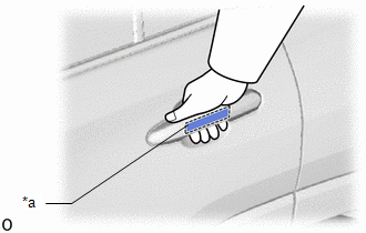
(i) Touch the unlock sensor on the backside of the rear door outside handle assembly LH.
HINT:
When checking the operation of the unlock sensor again, make sure to perform the procedure from step (a).
Body Electrical > Smart Key > Data List
|
Tester Display |
Measurement Item |
Range |
Normal Condition |
Diagnostic Note |
|---|---|---|---|---|
|
Dr-Door Touch Sensor |
Rear door LH touch sensor (unlock sensor) |
ON or OFF |
ON: Rear door LH touch sensor (unlock sensor) touched OFF: Rear door LH touch sensor (unlock sensor) not touched |
|
Body Electrical > Smart Key > Data List
|
Tester Display |
|---|
|
Dr-Door Touch Sensor |
OK:
The Techstream display changes correctly in response to the operation of the rear door outside handle assembly LH.
| OK |
|
|
|
4. |
CHECK HARNESS AND CONNECTOR (CERTIFICATION ECU (SMART KEY ECU ASSEMBLY) - REAR DOOR OUTSIDE HANDLE ASSEMBLY LH) |
(a) Disconnect the M7 certification ECU (smart key ECU assembly) connector.
(b) Disconnect the L6 rear door outside handle assembly LH connector.
(c) Measure the resistance according to the value(s) in the table below.
Standard Resistance:
|
Tester Connection |
Condition |
Specified Condition |
|---|---|---|
|
M7-1 (CLG3) - L6-6 (ANT1) |
Always |
Below 1 Ω |
|
M7-2 (CG3B) - L6-4 (ANT2) |
Always |
Below 1 Ω |
|
M7-1 (CLG3) or L6-6 (ANT1) - Other terminals and body ground |
Always |
10 kΩ or higher |
|
M7-2 (CG3B) or L6-4 (ANT2) - Other terminals and body ground |
Always |
10 kΩ or higher |
(d) Reconnect the L6 rear door outside handle assembly LH connector.
(e) Reconnect the M7 certification ECU (smart key ECU assembly) connector.
| NG |
|
REPAIR OR REPLACE HARNESS OR CONNECTOR |
|
|
5. |
CHECK REAR DOOR OUTSIDE HANDLE ASSEMBLY LH (INPUT TO REAR DOOR LH UNLOCK SENSOR) |
|
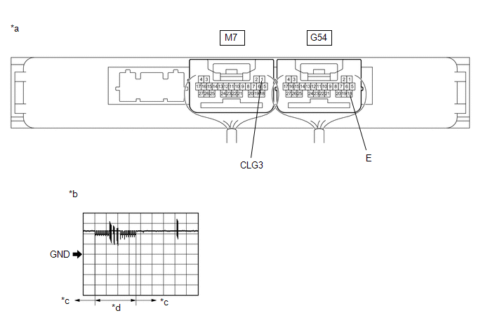
*a |
Component with harness connected (Certification ECU (Smart Key ECU Assembly)) |
*b |
Waveform 1 |
|
*c |
Unlock sensor not touched |
*d |
Unlock sensor touched |
(a) Using an oscilloscope, check the waveform.
OK:
|
Tester Connection |
Condition |
Tool Setting |
Specified Condition |
|---|---|---|---|
|
M7-1 (CLG3) - G54-18 (E) |
Procedure: |
5 V/DIV., 50 ms/DIV. |
Pulse generation (See waveform 1) |
| OK |
|
| NG |
|
|
|
|