| Last Modified: 05-08-2025 | 6.11:8.1.0 | Doc ID: RM100000002PXZJ |
| Model Year Start: 2024 | Model: RAV4 | Prod Date Range: [10/2023 - 11/2024] |
| Title: LIGHTING (EXT): LIGHTING SYSTEM: Taillight Relay Circuit; 2024 MY RAV4 RAV4 HV [10/2023 - 11/2024] | ||
|
Taillight Relay Circuit |
DESCRIPTION
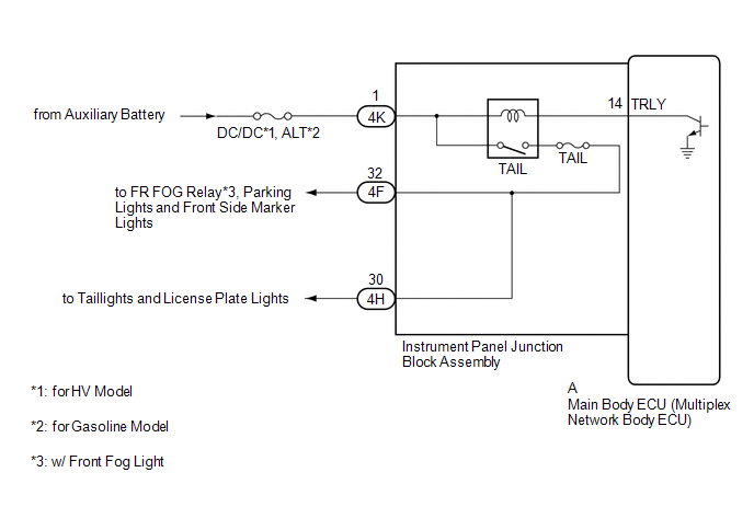
The main body ECU (multiplex network body ECU) controls the operation of the TAIL relay.
WIRING DIAGRAM
CAUTION / NOTICE / HINT
NOTICE:
- Inspect the fuses for circuits related to this system before performing the following procedure.
-
w/ Smart Key System:
Before replacing the main body ECU (multiplex network body ECU), refer to Registration.
PROCEDURE
|
1. |
CONFIRM MODEL |
(a) Choose the model to be inspected.
|
Result |
Proceed to |
|---|---|
|
Type A |
A |
|
Type B |
B |
| B |

|
|

|
2. |
PERFORM ACTIVE TEST USING TECHSTREAM |
(a) Connect the Techstream to the DLC3.
(b) Turn the ignition switch to ON.
(c) Turn the Techstream on.
(d) Enter the following menus: Body Electrical / Main Body / Active Test.
(e) Perform the Active Test according to the display on the Techstream.
Body Electrical > Main Body > Active Test
|
Tester Display |
Measurement Item |
Control Range |
Diagnostic Note |
|---|---|---|---|
|
Taillight / Clearance Light |
Taillight relay |
OFF or ON |
- |
Body Electrical > Main Body > Active Test
|
Tester Display |
|---|
|
Taillight / Clearance Light |
OK:
Taillights illuminate.
| OK |
|
PROCEED TO NEXT SUSPECTED AREA SHOWN IN PROBLEM SYMPTOMS TABLE |
| NG |
|
|
3. |
PERFORM ACTIVE TEST USING TECHSTREAM |
(a) Connect the Techstream to the DLC3.
(b) Turn the ignition switch to ON.
(c) Turn the Techstream on.
(d) Enter the following menus: Body Electrical / Main Body / Active Test.
(e) Perform the Active Test according to the display on the Techstream.
Body Electrical > Main Body > Active Test
|
Tester Display |
Measurement Item |
Control Range |
Diagnostic Note |
|---|---|---|---|
|
Taillight Relay |
Taillight relay |
OFF or ON |
- |
Body Electrical > Main Body > Active Test
|
Tester Display |
|---|
|
Taillight Relay |
OK:
Taillights illuminate.
| OK |
|
PROCEED TO NEXT SUSPECTED AREA SHOWN IN PROBLEM SYMPTOMS TABLE |
|
|
4. |
CHECK HARNESS AND CONNECTOR (INSTRUMENT PANEL JUNCTION BLOCK ASSEMBLY - BATTERY) |
|
(a) Disconnect the instrument panel junction block assembly connector. |
|
(b) Measure the voltage according to the value(s) in the table below.
Standard Voltage:
|
Tester Connection |
Switch Condition |
Specified Condition |
|---|---|---|
|
4K-1 - Body ground |
Ignition switch off |
11 to 14 V |
| NG |
|
REPAIR OR REPLACE HARNESS OR CONNECTOR |
|
|
5. |
INSPECT INSTRUMENT PANEL JUNCTION BLOCK ASSEMBLY |
|
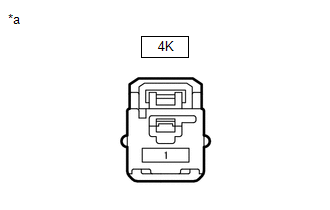
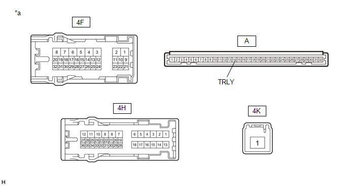
*a |
Component without harness connected (Instrument Panel Junction Block Assembly) |
- |
- |
(a) Remove the instrument panel junction block assembly.
Click here
![2024 - 2025 MY RAV4 RAV4 HV [10/2023 - ]; POWER DISTRIBUTION: MAIN BODY ECU: REMOVAL](/t3Portal/stylegraphics/info.gif)
(b) Remove the main body ECU (multiplex network body ECU) from the instrument panel junction block assembly.
(c) Connect a positive (+) lead from the auxiliary battery to terminal 4K-1.
(d) Connect a negative (-) lead from the auxiliary battery to terminal A-14 (TRLY).
(e) Measure the voltage according to the value(s) in the table below.
Standard Voltage:
|
Tester Connection |
Condition |
Specified Condition |
|---|---|---|
|
4F-32 - Auxiliary battery negative (-) terminal |
Auxiliary battery voltage is applied between terminals 4K-1 - A-14 (TRLY) |
11 to 14 V |
|
4H-30 - Auxiliary battery negative (-) terminal |
Auxiliary battery voltage is applied between terminals 4K-1 - A-14 (TRLY) |
11 to 14 V |
| OK |
|
| NG |
|
|
|
|