- DTC B1206, B1273*3, B2321, B2322, B2323 or B2324 are output*2
- DTC B120687, B127387*3, B232187, B232287, B232387 or B232487 are output*1
| Last Modified: 11-18-2025 | 6.11:8.1.0 | Doc ID: RM100000002Q1SB |
| Model Year Start: 2024 | Model: RAV4 | Prod Date Range: [10/2023 - 11/2024] |
| Title: NETWORKING: LIN COMMUNICATION SYSTEM: B1206,B120687,B1273,B127387,B2321,B232187,B2322,B232287,B2323,B232387,B2324,B232487; P/W Master Switch Communication Stop; 2024 MY RAV4 RAV4 HV [10/2023 - 11/2024] | ||
|
DTC |
B1206 |
P/W Master Switch Communication Stop |
|
DTC |
B120687 |
P/W Master SW System Missing Message |
|
DTC |
B1273 |
Sliding Roof ECU Communication Stop |
|
DTC |
B127387 |
Sliding Roof System Missing Message |
|
DTC |
B2321 |
D-Door Motor ECU Communication Stop |
|
DTC |
B232187 |
D-Door P/W System Missing Message |
|
DTC |
B2322 |
P-Door Motor ECU Communication Stop |
|
DTC |
B232287 |
P-Door P/W System Missing Message |
|
DTC |
B2323 |
RR-Door Motor ECU Communication Stop |
|
DTC |
B232387 |
RR-Door P/W System Missing Message |
|
DTC |
B2324 |
RL-Door Motor ECU Communication Stop |
|
DTC |
B232487 |
RL-Door P/W System Missing Message |
DESCRIPTION
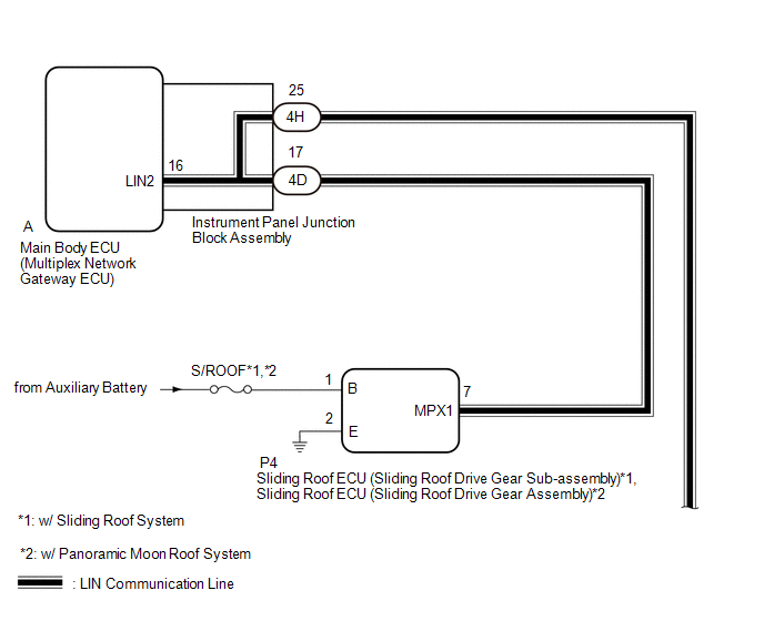
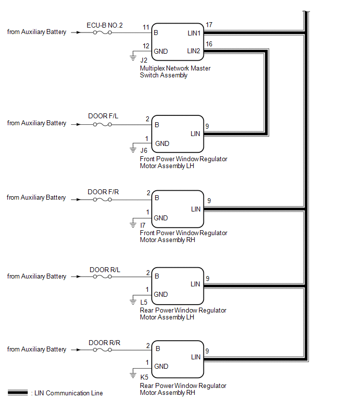
This DTC is stored when LIN communication between the main body ECU (multiplex network body ECU) and multiplex network master switch assembly, front power window regulator motor assembly LH, front power window regulator motor assembly RH, rear power window regulator motor assembly RH, rear power window regulator motor assembly LH, sliding roof ECU (sliding roof drive gear sub-assembly)*1 or sliding roof ECU (sliding roof drive gear assembly)*2 stops for 10 seconds or more.
- *1: w/ Sliding Roof System
- *2: w/ Panoramic Moon Roof System
|
DTC No. |
Detection Item |
DTC Detection Condition |
Trouble Area |
|---|---|---|---|
|
B1206 |
P/W Master Switch Communication Stop |
No communication between multiplex network master switch assembly and main body ECU (multiplex network body ECU) for 10 seconds or more. |
|
|
B120687 |
P/W Master SW System Missing Message |
No communication between multiplex network master switch assembly and main body ECU (multiplex network body ECU) for 10 seconds or more. |
|
|
B1273 |
Sliding Roof ECU Communication Stop |
No communication between sliding roof ECU (sliding roof drive gear sub-assembly) and main body ECU (multiplex network body ECU) for 10 seconds or more. |
|
|
B127387 |
Sliding Roof System Missing Message |
No communication between sliding roof ECU (sliding roof drive gear sub-assembly) and main body ECU (multiplex network body ECU) for 10 seconds or more. |
|
|
B2321 |
D-Door Motor ECU Communication Stop |
No communication between front power window regulator motor assembly LH and main body ECU (multiplex network body ECU) for 10 seconds or more. |
|
|
B232187 |
D-Door P/W System Missing Message |
No communication between front power window regulator motor assembly LH and main body ECU (multiplex network body ECU) for 10 seconds or more. |
|
|
B2322 |
P-Door Motor ECU Communication Stop |
No communication between front power window regulator motor assembly RH and main body ECU (multiplex network body ECU) for 10 seconds or more. |
|
|
B232287 |
P-Door P/W System Missing Message |
No communication between front power window regulator motor assembly RH and main body ECU (multiplex network body ECU) for 10 seconds or more. |
|
|
B2323 |
RR-Door Motor ECU Communication Stop |
No communication between rear power window regulator motor assembly RH and main body ECU (multiplex network body ECU) for 10 seconds or more. |
|
|
B232387 |
RR-Door P/W System Missing Message |
No communication between rear power window regulator motor assembly RH and main body ECU (multiplex network body ECU) for 10 seconds or more. |
|
|
B2324 |
RL-Door Motor ECU Communication Stop |
No communication between rear power window regulator motor assembly LH and main body ECU (multiplex network body ECU) for 10 seconds or more. |
|
|
B232487 |
RL-Door P/W System Missing Message |
No communication between rear power window regulator motor assembly LH and main body ECU (multiplex network body ECU) for 10 seconds or more. |
|
WIRING DIAGRAM
CAUTION / NOTICE / HINT
NOTICE:
- Inspect the fuses for circuits related to this system before performing the following procedure.
-
When a power window regulator motor assembly is replaced or removed and reinstalled, it is necessary to perform initialization.
Click here
![2019 - 2025 MY RAV4 RAV4 HV [11/2018 - ]; WINDOW / GLASS: POWER WINDOW CONTROL SYSTEM: INITIALIZATION](/t3Portal/stylegraphics/info.gif)
-
Before replacing the main body ECU (multiplex network body ECU), refer to Registration.
for HV Model: Click here
for Gasoline Model: Click here
-
The different types of main body ECU (multiplex network ECU) are shown in the "PRECAUTION".
Click here
PROCEDURE
PROCEDURE
|
1. |
CHECK FOR DTC |
(a) Clear the DTCs.
Click here
for Type A:
Body Electrical > Main Body > Clear DTCs
for Type B:
Body Electrical > Main Body > Clear DTCs
(b) Check for DTCs.
Click here
for Type A:
Body Electrical > Main Body > Trouble Codes
for Type B:
Body Electrical > Main Body > Trouble Codes
|
Result |
Proceed to |
|---|---|
|
DTC is not output |
A |
|
DTC B2325*2 or B232588*1 is output |
B |
|
|
C |
| A |

|
| B |
|
| C |
|
|
2. |
CHECK FOR VEHICLE TYPE |
(a) Check the vehicle type.
|
Result |
Proceed to |
|---|---|
|
The vehicle with Sliding Roof System or Panoramic Moon Roof System |
A |
|
The vehicle without Sliding Roof System and Panoramic Moon Roof System |
B |
| B |
|
|

|
3. |
CHECK FOR DTC |
(a) Check for DTCs.
Click here
for Type A:
Body Electrical > Main Body > Trouble Codes
for Type B:
Body Electrical > Main Body > Trouble Codes
|
Result |
Proceed to |
|---|---|
|
A |
|
Only DTC B1273*2 or B127387*1 is output |
B |
|
C |
|
D |
|
Only DTC B1206*2 or B120687*1 is output |
E |
|
Only DTC B2321*2 or B232187*1 is output |
F |
|
Only DTC B2322*2 or B232287*1 is output |
G |
|
Only DTC B2323*2 or B232387*1 is output |
H |
|
Only DTC B2324*2 or B232487*1 is output |
I |
| A |
|
| C |
|
| D |
|
| E |
|
| F |
|
| G |
|
| H |
|
| I |
|
|
|
4. |
INSPECT INSTRUMENT PANEL JUNCTION BLOCK ASSEMBLY |
(a) Remove the instrument panel junction block assembly.
Click here
|
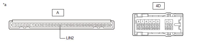
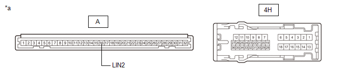
*a |
Component without harness connected (Instrument Panel Junction Block Assembly) |
- |
- |
(b) Remove the main body ECU (multiplex network body ECU) from the instrument panel junction block assembly.
(c) Measure the resistance according to the value(s) in the table below.
Standard Resistance:
|
Tester Connection |
Condition |
Specified Condition |
|---|---|---|
|
4D-17 - A-16 (LIN2) |
Always |
Below 1 Ω |
|
Result |
Proceed to |
|---|---|
|
OK (w/ Sliding Roof System) |
A |
|
OK (w/ Panoramic Moon Roof System) |
B |
|
NG |
C |
| C |
|
| B |
|
|
|
5. |
CHECK HARNESS AND CONNECTOR (INSTRUMENT PANEL JUNCTION BLOCK ASSEMBLY - SLIDING ROOF ECU [SLIDING ROOF DRIVE GEAR SUB-ASSEMBLY]) |
(a) Disconnect the 4D instrument panel junction block assembly connector.
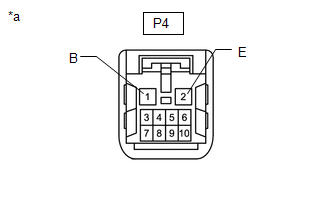
(b) Disconnect the P4 sliding roof ECU (sliding roof drive gear sub-assembly) connector.
(c) Measure the resistance according to the value(s) in the table below.
Standard Resistance:
|
Tester Connection |
Condition |
Specified Condition |
|---|---|---|
|
4D-17 - P4-7 (MPX1) |
Always |
Below 1 Ω |
| NG |
|
REPAIR OR REPLACE HARNESS OR CONNECTOR |
|
|
6. |
CHECK HARNESS AND CONNECTOR (SLIDING ROOF ECU [SLIDING ROOF DRIVE GEAR SUB-ASSEMBLY] POWER SOURCE CIRCUIT) |
|
(a) Disconnect the sliding roof ECU (sliding roof drive gear sub-assembly) connector. |
|
(b) Measure the voltage according to the value(s) in the table below.
Standard Voltage:
|
Tester Connection |
Switch Condition |
Specified Condition |
|---|---|---|
|
P4-1 (B) - Body ground |
Ignition switch off |
11 to 14 V |
(c) Measure the resistance according to the value(s) in the table below.
Standard Resistance:
|
Tester Connection |
Condition |
Specified Condition |
|---|---|---|
|
P4-2 (E) - Body ground |
Always |
Below 1 Ω |
| OK |
|
REPLACE SLIDING ROOF ECU (SLIDING ROOF DRIVE GEAR SUB-ASSEMBLY) |
| NG |
|
REPAIR OR REPLACE HARNESS OR CONNECTOR |
|
7. |
CHECK HARNESS AND CONNECTOR (INSTRUMENT PANEL JUNCTION BLOCK ASSEMBLY - SLIDING ROOF ECU [SLIDING ROOF DRIVE GEAR ASSEMBLY]) |
(a) Disconnect the 4D instrument panel junction block assembly connector.
(b) Disconnect the P4 sliding roof ECU (sliding roof drive gear assembly) connector.
(c) Measure the resistance according to the value(s) in the table below.
Standard Resistance:
|
Tester Connection |
Condition |
Specified Condition |
|---|---|---|
|
4D-17 - P4-7 (MPX1) |
Always |
Below 1 Ω |
| NG |
|
REPAIR OR REPLACE HARNESS OR CONNECTOR |
|
|
8. |
CHECK HARNESS AND CONNECTOR (SLIDING ROOF ECU [SLIDING ROOF DRIVE GEAR ASSEMBLY] POWER SOURCE CIRCUIT) |
|
(a) Disconnect the sliding roof ECU (sliding roof drive gear assembly) connector. |
|
(b) Measure the voltage according to the value(s) in the table below.
Standard Voltage:
|
Tester Connection |
Switch Condition |
Specified Condition |
|---|---|---|
|
P4-1 (B) - Body ground |
Ignition switch off |
11 to 14 V |
(c) Measure the resistance according to the value(s) in the table below.
Standard Resistance:
|
Tester Connection |
Condition |
Specified Condition |
|---|---|---|
|
P4-2 (E) - Body ground |
Always |
Below 1 Ω |
| OK |
|
| NG |
|
REPAIR OR REPLACE HARNESS OR CONNECTOR |
|
9. |
CHECK FOR DTC |
(a) Check for DTCs.
Click here
for Type A:
Body Electrical > Main Body > Trouble Codes
for Type B:
Body Electrical > Main Body > Trouble Codes
|
Result |
Proceed to |
|---|---|
|
A |
|
B |
|
Only DTC B1206*2 or B120687*1 is output |
C |
|
Only DTC B2321*2 or B232187*1 is output |
D |
|
Only DTC B2322*2 or B232287*1 is output |
E |
|
Only DTC B2323*2 or B232387*1 is output |
F |
|
Only DTC B2324*2 or B232487*1 is output |
G |
| B |
|
| C |
|
| D |
|
| E |
|
| F |
|
| G |
|
|
|
10. |
CHECK HARNESS AND CONNECTOR (INSTRUMENT PANEL JUNCTION BLOCK ASSEMBLY - MULTIPLEX NETWORK MASTER SWITCH ASSEMBLY) |
(a) Disconnect the 4H instrument panel junction block assembly connector.
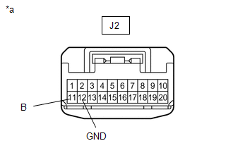
(b) Disconnect the J2 multiplex network master switch assembly connector.
(c) Measure the resistance according to the value(s) in the table below.
Standard Resistance:
|
Tester Connection |
Condition |
Specified Condition |
|---|---|---|
|
4H-25 - J2-17 (LIN1) |
Always |
Below 1 Ω |
| NG |
|
REPAIR OR REPLACE HARNESS OR CONNECTOR |
|
|
11. |
INSPECT INSTRUMENT PANEL JUNCTION BLOCK ASSEMBLY |
(a) Remove the instrument panel junction block assembly.
Click here
|
*a |
Component without harness connected (Instrument Panel Junction Block Assembly) |
- |
- |
(b) Remove the main body ECU (multiplex network body ECU) from the instrument panel junction block assembly.
(c) Measure the resistance according to the value(s) in the table below.
Standard Resistance:
|
Tester Connection |
Condition |
Specified Condition |
|---|---|---|
|
4H-25 - A-16 (LIN2) |
Always |
Below 1 Ω |
| OK |
|
| NG |
|
|
12. |
CHECK HARNESS AND CONNECTOR (INSTRUMENT PANEL JUNCTION BLOCK ASSEMBLY - MULTIPLEX NETWORK MASTER SWITCH ASSEMBLY) |
(a) Disconnect the 4H instrument panel junction block assembly connector.
(b) Disconnect the J2 multiplex network master switch assembly connector.
(c) Measure the resistance according to the value(s) in the table below.
Standard Resistance:
|
Tester Connection |
Condition |
Specified Condition |
|---|---|---|
|
4H-25 - J2-17 (LIN1) |
Always |
Below 1 Ω |
| OK |
|
| NG |
|
REPAIR OR REPLACE HARNESS OR CONNECTOR |
|
13. |
CHECK HARNESS AND CONNECTOR (MULTIPLEX NETWORK MASTER SWITCH ASSEMBLY POWER SOURCE CIRCUIT) |
|
(a) Disconnect the multiplex network master switch assembly connector. |
|
(b) Measure the voltage according to the value(s) in the table below.
Standard Voltage:
|
Tester Connection |
Switch Condition |
Specified Condition |
|---|---|---|
|
J2-11 (B) - Body ground |
Ignition switch off |
11 to 14 V |
(c) Measure the resistance according to the value(s) in the table below.
Standard Resistance:
|
Tester Connection |
Condition |
Specified Condition |
|---|---|---|
|
J2-12 (GND) - Body ground |
Always |
Below 1 Ω |
| OK |
|
| NG |
|
REPAIR OR REPLACE HARNESS OR CONNECTOR |
|
14. |
CHECK HARNESS AND CONNECTOR (INSTRUMENT PANEL JUNCTION BLOCK ASSEMBLY - FRONT POWER WINDOW REGULATOR MOTOR ASSEMBLY LH) |
(a) Disconnect the 4H instrument panel junction block assembly connector.
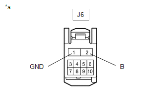
(b) Disconnect the J6 front power window regulator motor assembly LH connector.
(c) Measure the resistance according to the value(s) in the table below.
Standard Resistance:
|
Tester Connection |
Condition |
Specified Condition |
|---|---|---|
|
4H-25 - J6-9 (LIN) |
Always |
Below 1 Ω |
| NG |
|
|
|
15. |
CHECK HARNESS AND CONNECTOR (FRONT POWER WINDOW REGULATOR MOTOR ASSEMBLY LH POWER SOURCE CIRCUIT) |
|
(a) Disconnect the front power window regulator motor assembly LH connector. |
|
(b) Measure the voltage according to the value(s) in the table below.
Standard Voltage:
|
Tester Connection |
Switch Condition |
Specified Condition |
|---|---|---|
|
J6-2 (B) - Body ground |
Ignition switch off |
11 to 14 V |
(c) Measure the resistance according to the value(s) in the table below.
Standard Resistance:
|
Tester Connection |
Condition |
Specified Condition |
|---|---|---|
|
J6-1 (GND) - Body ground |
Always |
Below 1 Ω |
| OK |
|
| NG |
|
REPAIR OR REPLACE HARNESS OR CONNECTOR |
|
16. |
CHECK HARNESS AND CONNECTOR (MULTIPLEX NETWORK MASTER SWITCH ASSEMBLY - FRONT POWER WINDOW REGULATOR MOTOR ASSEMBLY LH) |
(a) Disconnect the J2 multiplex network master switch assembly connector.
(b) Disconnect the J6 front power window regulator motor assembly LH connector.
(c) Measure the resistance according to the value(s) in the table below.
Standard Resistance:
|
Tester Connection |
Condition |
Specified Condition |
|---|---|---|
|
J2-16 (LIN2) - J6-9 (LIN) |
Always |
Below 1 Ω |
| OK |
|
| NG |
|
REPAIR OR REPLACE HARNESS OR CONNECTOR |
|
17. |
CHECK HARNESS AND CONNECTOR (INSTRUMENT PANEL JUNCTION BLOCK ASSEMBLY - FRONT POWER WINDOW REGULATOR MOTOR ASSEMBLY RH) |
(a) Disconnect the 4H instrument panel junction block assembly connector.
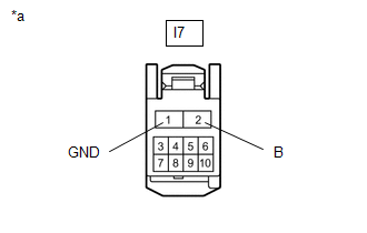
(b) Disconnect the I7 front power window regulator motor assembly RH connector.
(c) Measure the resistance according to the value(s) in the table below.
Standard Resistance:
|
Tester Connection |
Condition |
Specified Condition |
|---|---|---|
|
4H-25 - I7-9 (LIN) |
Always |
Below 1 Ω |
| NG |
|
REPAIR OR REPLACE HARNESS OR CONNECTOR |
|
|
18. |
CHECK HARNESS AND CONNECTOR (FRONT POWER WINDOW REGULATOR MOTOR ASSEMBLY RH POWER SOURCE CIRCUIT) |
|
(a) Disconnect the front power window regulator motor assembly RH connector. |
|
(b) Measure the voltage according to the value(s) in the table below.
Standard Voltage:
|
Tester Connection |
Switch Condition |
Specified Condition |
|---|---|---|
|
I7-2 (B) - Body ground |
Ignition switch off |
11 to 14 V |
(c) Measure the resistance according to the value(s) in the table below.
Standard Resistance:
|
Tester Connection |
Condition |
Specified Condition |
|---|---|---|
|
I7-1 (GND) - Body ground |
Always |
Below 1 Ω |
| OK |
|
| NG |
|
REPAIR OR REPLACE HARNESS OR CONNECTOR |
|
19. |
CHECK HARNESS AND CONNECTOR (INSTRUMENT PANEL JUNCTION BLOCK ASSEMBLY - REAR POWER WINDOW REGULATOR MOTOR ASSEMBLY RH) |
(a) Disconnect the 4H instrument panel junction block assembly connector.
(b) Disconnect the K5 rear power window regulator motor assembly RH connector.
(c) Measure the resistance according to the value(s) in the table below.
Standard Resistance:
|
Tester Connection |
Condition |
Specified Condition |
|---|---|---|
|
4H-25 - K5-9 (LIN) |
Always |
Below 1 Ω |
| NG |
|
REPAIR OR REPLACE HARNESS OR CONNECTOR |
|
|
20. |
CHECK HARNESS AND CONNECTOR (REAR POWER WINDOW REGULATOR MOTOR ASSEMBLY RH POWER SOURCE CIRCUIT) |
|
(a) Disconnect the rear power window regulator motor assembly RH connector. |
|
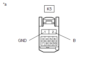
(b) Measure the voltage according to the value(s) in the table below.
Standard Voltage:
|
Tester Connection |
Switch Condition |
Specified Condition |
|---|---|---|
|
K5-2 (B) - Body ground |
Ignition switch off |
11 to 14 V |
(c) Measure the resistance according to the value(s) in the table below.
Standard Resistance:
|
Tester Connection |
Condition |
Specified Condition |
|---|---|---|
|
K5-1 (GND) - Body ground |
Always |
Below 1 Ω |
| OK |
|
| NG |
|
REPAIR OR REPLACE HARNESS OR CONNECTOR |
|
21. |
CHECK HARNESS AND CONNECTOR (INSTRUMENT PANEL JUNCTION BLOCK ASSEMBLY - REAR POWER WINDOW REGULATOR MOTOR ASSEMBLY LH) |
(a) Disconnect the 4H instrument panel junction block assembly connector.
(b) Disconnect the L5 rear power window regulator motor assembly LH connector.
(c) Measure the resistance according to the value(s) in the table below.
Standard Resistance:
|
Tester Connection |
Condition |
Specified Condition |
|---|---|---|
|
4H-25 - L5-9 (LIN) |
Always |
Below 1 Ω |
| NG |
|
REPAIR OR REPLACE HARNESS OR CONNECTOR |
|
|
22. |
CHECK HARNESS AND CONNECTOR (REAR POWER WINDOW REGULATOR MOTOR ASSEMBLY LH POWER SOURCE CIRCUIT) |
|
(a) Disconnect the rear power window regulator motor assembly LH connector. |
|
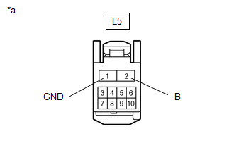
(b) Measure the voltage according to the value(s) in the table below.
Standard Voltage:
|
Tester Connection |
Switch Condition |
Specified Condition |
|---|---|---|
|
L5-2 (B) - Body ground |
Ignition switch off |
11 to 14 V |
(c) Measure the resistance according to the value(s) in the table below.
Standard Resistance:
|
Tester Connection |
Condition |
Specified Condition |
|---|---|---|
|
L5-1 (GND) - Body ground |
Always |
Below 1 Ω |
| OK |
|
| NG |
|
REPAIR OR REPLACE HARNESS OR CONNECTOR |
|
|
|