| Last Modified: 05-08-2025 | 6.11:8.1.0 | Doc ID: RM100000002Q2HA |
| Model Year Start: 2024 | Model: RAV4 | Prod Date Range: [10/2023 - ] |
| Title: LIGHTING (EXT): LIGHTING SYSTEM: B243900,B243A00; Headlight LH Circuit; 2024 - 2025 MY RAV4 RAV4 HV [10/2023 - ] | ||
|
DTC |
B243900 |
Headlight LH Circuit |
|
DTC |
B243A00 |
Headlight RH Circuit |
DESCRIPTION
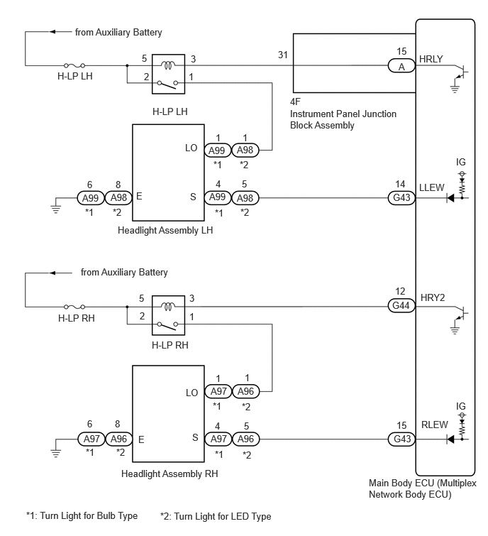
These DTCs are stored when the low beam headlights do not illuminate, or a communication malfunction is detected between the light control LED ECU and main body ECU (multiplex network body ECU).
|
DTC No. |
Detection Item |
DTC Detection Condition |
Trouble Area |
DTC Output from |
|---|---|---|---|---|
|
B243900 |
Headlight LH Circuit |
Detection condition:
Malfunction status:
Malfunction duration:
|
|
Main Body |
|
B243A00 |
Headlight RH Circuit |
Detection condition:
Malfunction status:
Malfunction duration:
|
|
Main Body |
WIRING DIAGRAM
CAUTION / NOTICE / HINT
NOTICE:
- Inspect the fuses for circuits related to this system before performing the following procedure.
- Before replacing the main body ECU (multiplex network body ECU), refer to Registration.
PROCEDURE
|
1. |
CLEAR DTC |
(a) Clear the DTCs.
Body Electrical > Main Body > Clear DTCs
|

|
2. |
CHECK FOR DTC |
(a) Connect the Techstream to the DLC3.
(b) Turn the ignition switch to ON (READY).
(c) Operate the light control switch to turn on the low beam headlights and wait 10 seconds or more.
(d) Turn the Techstream on.
(e) Enter the following menus: Body Electrical / Main Body / Trouble Codes.
(f) Check for DTCs.
Body Electrical > Main Body > Trouble Codes
OK:
DTC B2430 and B2431 are not output.
|
Result |
Proceed to |
|---|---|
|
OK |
A |
|
NG (DTC B2430 is output) |
B |
|
NG (DTC B2431 is output) |
C |
| A |

|
| C |
|
|
|
3. |
CHECK VEHICLE TYPE |
|
Result |
Proceed to |
|---|---|
|
Turn Light for Bulb Type |
A |
|
Turn Light for LED Type |
B |
| B |
|
|
|
4. |
CHECK HEADLIGHT ASSEMBLY LH (LO TERMINAL VOLTAGE) |
|
(a) Disconnect the headlight assembly LH connector. |
|

(b) Measure the voltage according to the value(s) in the table below.
Standard Voltage:
|
Tester Connection |
Switch Condition |
Specified Condition |
|---|---|---|
|
A99-1 (LO) - Body ground |
Light control switch in HEAD position |
11 to 14 V |
| NG |
|
|
|
5. |
CHECK HARNESS AND CONNECTOR (HEADLIGHT ASSEMBLY LH - BODY GROUND) |
|
(a) Disconnect the headlight assembly LH connector. |
|
(b) Measure the resistance according to the value(s) in the table below.
Standard Resistance:
|
Tester Connection |
Condition |
Specified Condition |
|---|---|---|
|
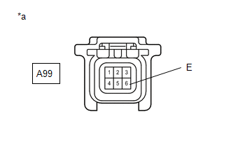
A99-6 (E) - Body ground |
Always |
Below 1 Ω |
| NG |
|
REPAIR OR REPLACE HARNESS OR CONNECTOR |
|
|
6. |
CHECK HEADLIGHT ASSEMBLY LH (S TERMINAL VOLTAGE) |
|
(a) Disconnect the headlight assembly LH connector. |
|
(b) Measure the voltage according to the value(s) in the table below.
Standard Voltage:
|
Tester Connection |
Switch Condition |
Specified Condition |
|---|---|---|
|
A99-4 (S) - Body ground |
Ignition switch ON |
11 to 14 V |
| OK |
|
|
|
7. |
CHECK HARNESS AND CONNECTOR (HEADLIGHT ASSEMBLY LH - MAIN BODY ECU (MULTIPLEX NETWORK BODY ECU)) |
(a) Disconnect the A99 headlight assembly LH connector.
(b) Disconnect the G43 main body ECU (multiplex network body ECU) connector.
(c) Measure the resistance according to the value(s) in the table below.
Standard Resistance:
|
Tester Connection |
Condition |
Specified Condition |
|---|---|---|
|
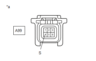
A99-4 (S) - G43-14 (LLEW) |
Always |
Below 1 Ω |
|
A99-4 (S) or G43-14 (LLEW) - Body ground |
Always |
10 kΩ or higher |
| OK |
|
| NG |
|
REPAIR OR REPLACE HARNESS OR CONNECTOR |
|
8. |
CHECK HARNESS AND CONNECTOR (H-LP LH RELAY - HEADLIGHT ASSEMBLY LH) |
(a) Remove the H-LP LH relay.
(b) Disconnect the A99 headlight assembly LH connector.
(c) Measure the resistance according to the value(s) in the table below.
Standard Resistance:
|
Tester Connection |
Condition |
Specified Condition |
|---|---|---|
|
3 (H-LP LH relay) - A99-1 (LO) |
Always |
Below 1 Ω |
|
3 (H-LP LH relay) or A99-1 (LO) - Body ground |
Always |
10 kΩ or higher |
| OK |
|
| NG |
|
REPAIR OR REPLACE HARNESS OR CONNECTOR |
|
9. |
CHECK HEADLIGHT ASSEMBLY LH (LO TERMINAL VOLTAGE) |
|
(a) Disconnect the headlight assembly LH connector. |
|
(b) Measure the voltage according to the value(s) in the table below.
Standard Voltage:
|
Tester Connection |
Switch Condition |
Specified Condition |
|---|---|---|
|
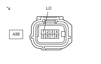
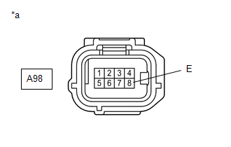
A98-1 (LO) - Body ground |
Light control switch in HEAD position |
11 to 14 V |
| NG |
|
|
|
10. |
CHECK HARNESS AND CONNECTOR (HEADLIGHT ASSEMBLY LH - BODY GROUND) |
|
(a) Disconnect the headlight assembly LH connector. |
|
(b) Measure the resistance according to the value(s) in the table below.
Standard Resistance:
|
Tester Connection |
Condition |
Specified Condition |
|---|---|---|
|
A98-8 (E) - Body ground |
Always |
Below 1 Ω |
| NG |
|
REPAIR OR REPLACE HARNESS OR CONNECTOR |
|
|
11. |
CHECK HEADLIGHT ASSEMBLY LH (S TERMINAL VOLTAGE) |
|
(a) Disconnect the headlight assembly LH connector. |
|
(b) Measure the voltage according to the value(s) in the table below.
Standard Voltage:
|
Tester Connection |
Switch Condition |
Specified Condition |
|---|---|---|
|
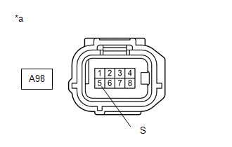
A98-5 (S) - Body ground |
Ignition switch ON |
11 to 14 V |
| OK |
|
|
|
12. |
CHECK HARNESS AND CONNECTOR (HEADLIGHT ASSEMBLY LH - MAIN BODY ECU (MULTIPLEX NETWORK BODY ECU)) |
(a) Disconnect the A98 headlight assembly LH connector.
(b) Disconnect the G43 main body ECU (multiplex network body ECU) connector.
(c) Measure the resistance according to the value(s) in the table below.
Standard Resistance:
|
Tester Connection |
Condition |
Specified Condition |
|---|---|---|
|
A98-5 (S) - G43-14 (LLEW) |
Always |
Below 1 Ω |
|
A98-5 (S) or G43-14 (LLEW) - Body ground |
Always |
10 kΩ or higher |
| OK |
|
| NG |
|
REPAIR OR REPLACE HARNESS OR CONNECTOR |
|
13. |
CHECK HARNESS AND CONNECTOR (H-LP LH RELAY - HEADLIGHT ASSEMBLY LH) |
(a) Remove the H-LP LH relay.
(b) Disconnect the A98 headlight assembly LH connector.
(c) Measure the resistance according to the value(s) in the table below.
Standard Resistance:
|
Tester Connection |
Condition |
Specified Condition |
|---|---|---|
|
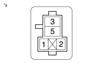
3 (H-LP LH relay) - A98-1 (LO) |
Always |
Below 1 Ω |
|
3 (H-LP LH relay) or A98-1 (LO) - Body ground |
Always |
10 kΩ or higher |
| NG |
|
REPAIR OR REPLACE HARNESS OR CONNECTOR |
|
|
14. |
INSPECT H-LP LH RELAY |
(a) Remove the H-LP LH relay.
(b) Inspect the H-LP LH relay.
Click here
![2019 - 2025 MY RAV4 RAV4 HV [02/2019 - ]; LIGHTING (EXT): RELAY: ON-VEHICLE INSPECTION](/t3Portal/stylegraphics/info.gif)
| NG |
|
REPLACE H-LP LH RELAY |
|
|
15. |
CHECK HARNESS AND CONNECTOR (POWER SOURCE - H-LP LH RELAY) |
(a) Remove the H-LP LH relay.
|
(b) Measure the voltage according to the value(s) in the table below. Standard Voltage:
|
|
| NG |
|
REPAIR OR REPLACE HARNESS OR CONNECTOR |
|
|
16. |
CHECK HARNESS AND CONNECTOR (H-LP LH RELAY - INSTRUMENT PANEL JUNCTION BLOCK ASSEMBLY) |
(a) Remove the H-LP LH relay.
(b) Disconnect the 4F instrument panel junction block assembly connector.
(c) Measure the resistance according to the value(s) in the table below.
Standard Resistance:
|
Tester Connection |
Condition |
Specified Condition |
|---|---|---|
|
1 (H-LP LH relay) - 4F-31 |
Always |
Below 1 Ω |
|
1 (H-LP LH relay) or 4F-31 - Body ground |
Always |
10 kΩ or higher |
| NG |
|
REPAIR OR REPLACE HARNESS OR CONNECTOR |
|
|
17. |
INSPECT INSTRUMENT PANEL JUNCTION BLOCK ASSEMBLY |
|
*a |
Component without harness connected (Instrument Panel Junction Block Assembly) |
- |
- |
(a) Remove the instrument panel junction block assembly.
Click here
(b) Remove the main body ECU (multiplex network body ECU) from the instrument panel junction block assembly.
(c) Measure the resistance according to the value(s) in the table below.
Standard Resistance:
|
Tester Connection |
Condition |
Specified Condition |
|---|---|---|
|
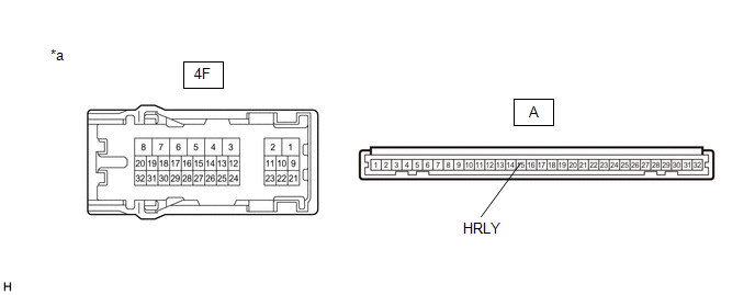
4F-31 - A-15 (HRLY) |
Always |
Below 1 Ω |
| OK |
|
| NG |
|
|
18. |
CHECK VEHICLE TYPE |
|
Result |
Proceed to |
|---|---|
|
Turn Light for Bulb Type |
A |
|
Turn Light for LED Type |
B |
| B |
|
|
|
19. |
CHECK HEADLIGHT ASSEMBLY RH (LO TERMINAL VOLTAGE) |
|
(a) Disconnect the headlight assembly RH connector. |
|
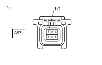
(b) Measure the voltage according to the value(s) in the table below.
Standard Voltage:
|
Tester Connection |
Condition |
Specified Condition |
|---|---|---|
|
A97-1 (LO) - Body ground |
Light control switch in HEAD position |
11 to 14 V |
| NG |
|
|
|
20. |
CHECK HARNESS AND CONNECTOR (HEADLIGHT ASSEMBLY RH - BODY GROUND) |
|
(a) Disconnect the headlight assembly RH connector. |
|
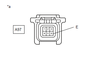
(b) Measure the resistance according to the value(s) in the table below.
Standard Resistance:
|
Tester Connection |
Condition |
Specified Condition |
|---|---|---|
|
A97-6 (E) - Body ground |
Always |
Below 1 Ω |
| NG |
|
REPAIR OR REPLACE HARNESS OR CONNECTOR |
|
|
21. |
INSPECT HEADLIGHT ASSEMBLY RH (S TERMINAL VOLTAGE) |
|
(a) Disconnect the headlight assembly RH connector. |
|

(b) Measure the voltage according to the value(s) in the table below.
Standard Voltage:
|
Tester Connection |
Switch Condition |
Specified Condition |
|---|---|---|
|
A97-4 (S) - Body ground |
Ignition switch ON |
11 to 14 V |
| OK |
|
|
|
22. |
CHECK HARNESS AND CONNECTOR (HEADLIGHT ASSEMBLY RH - MAIN BODY ECU (MULTIPLEX NETWORK BODY ECU)) |
(a) Disconnect the A97 headlight assembly RH connector.
(b) Disconnect the G43 main body ECU (multiplex network body ECU) connector.
(c) Measure the resistance according to the value(s) in the table below.
Standard Resistance:
|
Tester Connection |
Condition |
Specified Condition |
|---|---|---|
|
A97-4 (S) - G43-15 (RLEW) |
Always |
Below 1 Ω |
|
A97-4 (S) or G43-15 (RLEW) - Body ground |
Always |
10 kΩ or higher |
| OK |
|
| NG |
|
REPAIR OR REPLACE HARNESS OR CONNECTOR |
|
23. |
CHECK HARNESS AND CONNECTOR (H-LP RH RELAY - HEADLIGHT ASSEMBLY RH) |
(a) Remove the H-LP RH relay.
(b) Disconnect the A97 headlight assembly RH connector.
(c) Measure the resistance according to the value(s) in the table below.
Standard Resistance:
|
Tester Connection |
Condition |
Specified Condition |
|---|---|---|
|
3 (H-LP RH relay) - A97-1 (LO) |
Always |
Below 1 Ω |
|
3 (H-LP RH relay) or A97-1 (LO) - Body ground |
Always |
10 kΩ or higher |
| OK |
|
| NG |
|
REPAIR OR REPLACE HARNESS OR CONNECTOR |
|
24. |
CHECK HEADLIGHT ASSEMBLY RH (LO TERMINAL VOLTAGE) |
|
(a) Disconnect the headlight assembly RH connector. |
|
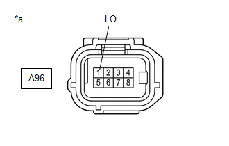
(b) Measure the voltage according to the value(s) in the table below.
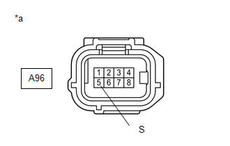
Standard Voltage:
|
Tester Connection |
Switch Condition |
Specified Condition |
|---|---|---|
|
A96-1 (LO) - Body ground |
Light control switch in HEAD position |
11 to 14 V |
| NG |
|
|
|
25. |
CHECK HARNESS AND CONNECTOR (HEADLIGHT ASSEMBLY RH - BODY GROUND) |
|
(a) Disconnect the headlight assembly RH connector. |
|
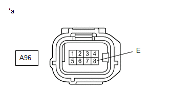
(b) Measure the resistance according to the value(s) in the table below.
Standard Resistance:
|
Tester Connection |
Condition |
Specified Condition |
|---|---|---|
|
A96-8 (E) - Body ground |
Always |
Below 1 Ω |
| NG |
|
REPAIR OR REPLACE HARNESS OR CONNECTOR |
|
|
26. |
CHECK HEADLIGHT ASSEMBLY LH (S TERMINAL VOLTAGE) |
|
(a) Disconnect the headlight assembly RH connector. |
|
(b) Measure the voltage according to the value(s) in the table below.
Standard Voltage:
|
Tester Connection |
Switch Condition |
Specified Condition |
|---|---|---|
|
A96-5 (S) - Body ground |
Ignition switch ON |
11 to 14 V |
| OK |
|
|
|
27. |
CHECK HARNESS AND CONNECTOR (HEADLIGHT ASSEMBLY RH - MAIN BODY ECU (MULTIPLEX NETWORK BODY ECU)) |
(a) Disconnect the A96 headlight assembly RH connector.
(b) Disconnect the G43 main body ECU (multiplex network body ECU) connector.
(c) Measure the resistance according to the value(s) in the table below.
Standard Resistance:
|
Tester Connection |
Condition |
Specified Condition |
|---|---|---|
|
A96-5 (S) - G43-14 (LLEW) |
Always |
Below 1 Ω |
|
A96-5 (S) or G43-14 (LLEW) - Body ground |
Always |
10 kΩ or higher |
| OK |
|
| NG |
|
REPAIR OR REPLACE HARNESS OR CONNECTOR |
|
28. |
CHECK HARNESS AND CONNECTOR (H-LP LH RELAY - HEADLIGHT ASSEMBLY RH) |
(a) Remove the H-LP RH relay.
(b) Disconnect the A96 headlight assembly RH connector.
(c) Measure the resistance according to the value(s) in the table below.
Standard Resistance:
|
Tester Connection |
Condition |
Specified Condition |
|---|---|---|
|
3 (H-LP RH relay) - A96-1 (LO) |
Always |
Below 1 Ω |
|
3 (H-LP RH relay) or A96-1 (LO) - Body ground |
Always |
10 kΩ or higher |
| NG |
|
REPAIR OR REPLACE HARNESS OR CONNECTOR |
|
|
29. |
INSPECT H-LP RH RELAY |
(a) Remove the H-LP RH relay.
(b) Inspect the H-LP RH relay.
Click here
| NG |
|
REPLACE H-LP RH RELAY |
|
|
30. |
CHECK HARNESS AND CONNECTOR (POWER SOURCE - H-LP RH RELAY) |
(a) Remove the H-LP RH relay.
|
(b) Measure the voltage according to the value(s) in the table below. Standard Voltage:
|
|
| NG |
|
REPAIR OR REPLACE HARNESS OR CONNECTOR |
|
|
31. |
CHECK HARNESS AND CONNECTOR (H-LP RH RELAY - MAIN BODY ECU (MULTIPLEX NETWORK BODY ECU)) |
(a) Remove the H-LP RH relay.
(b) Disconnect the G44 main body ECU (multiplex network body ECU) connector.
(c) Measure the resistance according to the value(s) in the table below.
Standard Resistance:
|
Tester Connection |
Condition |
Specified Condition |
|---|---|---|
|
1 (H-LP RH relay) - G44-12 (HRY2) |
Always |
Below 1 Ω |
|
1 (H-LP RH relay) or G44-12 (HRY2) - Body ground |
Always |
10 kΩ or higher |
| OK |
|
| NG |
|
REPAIR OR REPLACE HARNESS OR CONNECTOR |
|
|
|